

 Contact Us

 Home /
 Welding Positioners and External Axes: Why a Longer Robot Arm Is Often the Wrong Answer
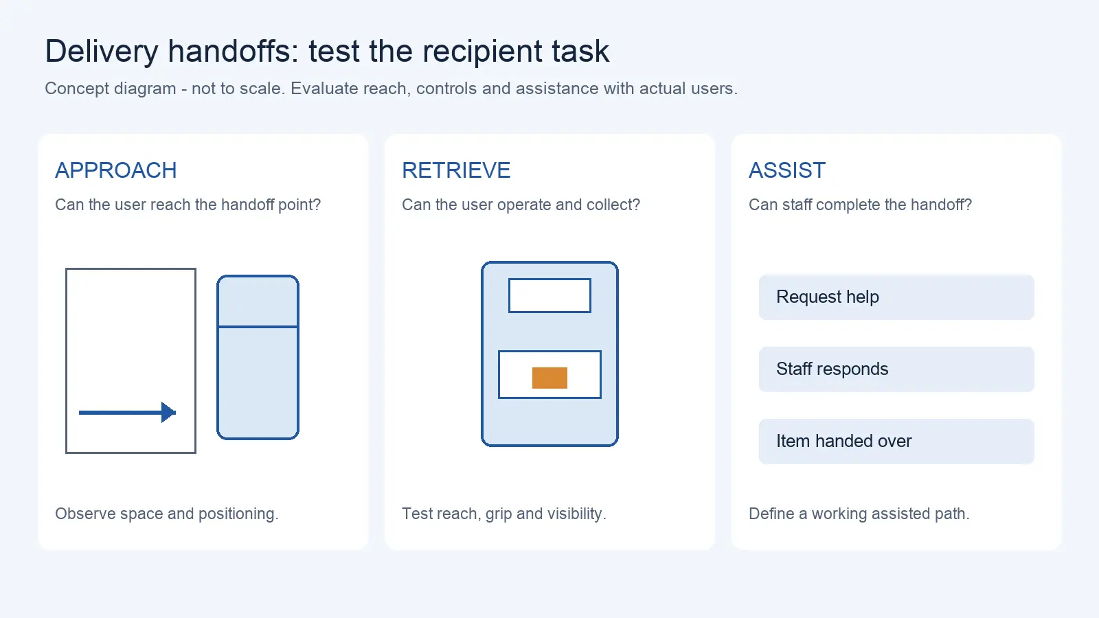
Delivery Robot Accessibility: Tray Reach, Controls, and Assisted Handoffs
Oct 12, 2026
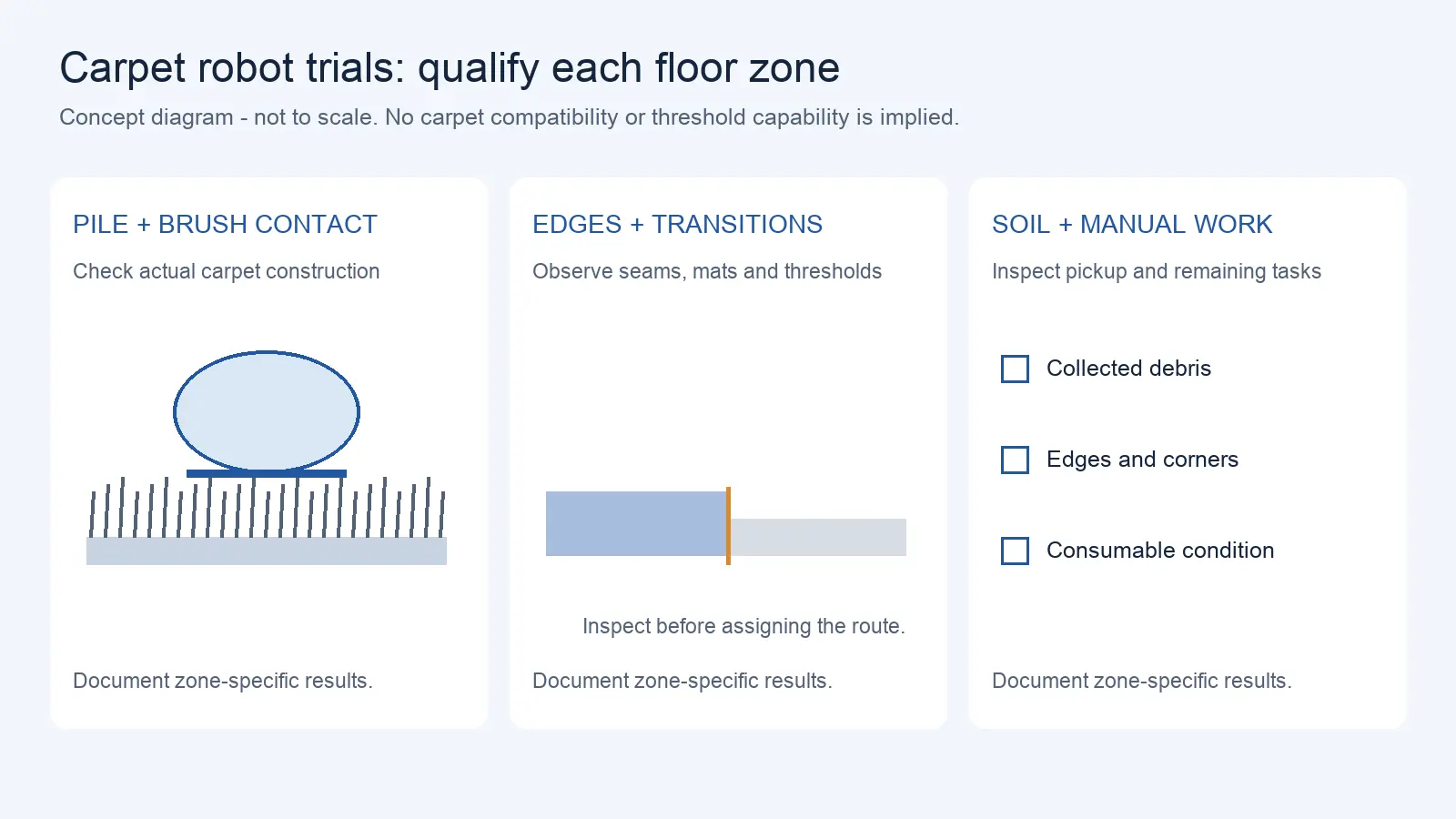
Commercial Carpet-Vacuuming Robots: Pile, Edge Transitions, and Maintenance Limits
Oct 12, 2026
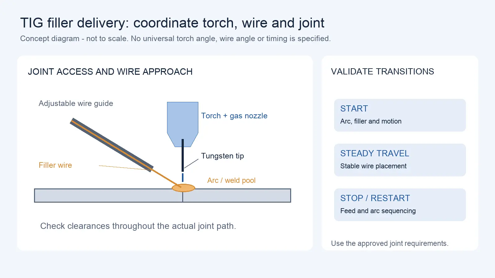
Robotic TIG Filler-Wire Delivery: Feed Angle, Arc Access, and Stop-Start Quality
Oct 12, 2026
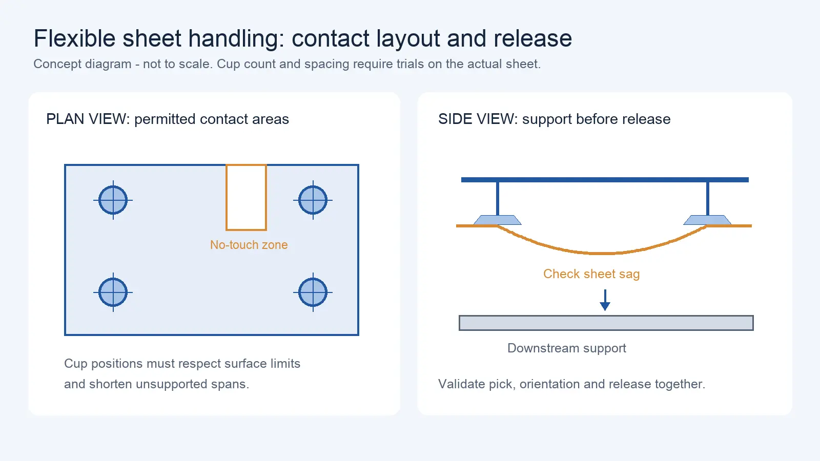
Suction Cup Layout for Flexible Sheets: Sag, Local Stress, and Controlled Release
Oct 12, 2026
When a welding robot cannot reach a joint at the correct angle, the instinctive response is to specify a robot with a longer reach. In many cases, this is the most expensive and least effective solution. A welding positioner or external axis brings the workpiece to the robot — rotating, tilting, or translating the part so the torch can access the joint at the optimal angle without extending the robot’s arm.
This article exists because the default response to a reach problem — buying a longer robot arm — is often the wrong answer. Positioners and external axes solve the orientation problem, which is usually the actual issue. This article covers positioner types, synchronized vs indexed positioning, and practical planning factors. For welding seam tracking technology (touch sensing, through-arc, vision), see Article 15. For robot programming method selection, see Article 13.
What follows explains the types of positioners and external axes available, the critical decision between synchronized and indexed positioning, and the practical factors that determine whether a positioner will solve your welding problem or introduce new ones.
The Core Problem: Torch Angle and Weld Position
In welding, the quality of the weld depends on the relationship between the torch angle, the weld pool, and gravity. Flat and horizontal welding positions (1G/2F) are generally easier to execute and produce more consistent results than overhead or vertical positions (3G/4G). A positioner’s primary function is to reorient the workpiece so the robot can weld in the most favorable position — regardless of where the joint sits on the actual part.
A robot with a 3-meter reach can theoretically access more of a large workpiece, but it will still weld at whatever angle the joint happens to be oriented. A positioner with a shorter robot can rotate the same workpiece so every joint is presented in a more favorable welding position. A positioner can reduce reach requirements and can improve access to favorable welding positions, depending on workpiece geometry and process requirements.
Key distinction: A longer arm extends the robot’s working envelope. A positioner changes the orientation of the workpiece within that envelope. These solve different problems — and the problem is usually orientation, not reach.
Positioner Types: Five Configurations
Rotary Table (Single-Axis)
A single-axis rotary table rotates the workpiece around one axis. This is the simplest and most common positioner type, suitable for circular welds, pipe circumferential joints, and multi-pass welding where the workpiece needs to rotate under a stationary torch.
Typical payload range: 100–5,000 kg (manufacturer-stated, varies by model)
Best for: Circular and circumferential welds; parts that need rotation around a single axis.
Limitation: Cannot tilt the workpiece — only rotation is available. If the joint requires a different welding position (e.g., rotating from flat to horizontal fillet), a single-axis table cannot achieve it.
Tilt-Rotate Table (Two-Axis)
A tilt-rotate table adds a second axis — tilt — to the rotation. The workpiece can be rotated and tilted to present almost any joint in the flat or horizontal position. This is the most versatile common positioner type.
Typical payload range: 500–2,000 kg (manufacturer-stated)
Best for: Complex 3D weldments, structural steel, pipe spools with multiple joint orientations.
Limitation: Payload capacity decreases as the tilt angle increases — the center of gravity shifts, creating higher moments on the tilt axis. Payload ratings are typically quoted for a specific center-of-gravity distance; exceeding that distance reduces the rated capacity.
Head-Tailstock
A head-tailstock configuration uses two centers — a driven headstock and an adjustable tailstock — to support long workpieces between centers. The workpiece rotates around its longitudinal axis.
Typical payload range: 1,000–10,000+ kg (manufacturer-stated)
Best for: Long workpieces — pipes, pressure vessels, tanks, wind tower sections.
Limitation: Only rotation around one axis (though some models add tilt). Setup requires aligning the tailstock with the workpiece centerline, which takes time for each new part type.
Linear Track (External 7th Axis)
A linear rail extends the robot’s working envelope along one axis. The robot mounts on a carriage that travels along the rail, allowing it to weld long parts or serve multiple stations.
Payload: Varies by robot and rail length.
Best for: Long workpieces that cannot be rotated (large panels, ship hulls); multi-station cells where one robot serves two or more fixtures.
Limitation: A linear track extends reach but does not change workpiece orientation. It is complementary to a positioner, not a replacement.
L-Type Lifting Positioner (Three-Axis)
An L-type positioner combines tilt, rotation, and lift — three axes of workpiece positioning. This provides the maximum flexibility for presenting joints at optimal welding angles.
Typical payload range: 500–2,000 kg (manufacturer-stated)
Best for: Complex weldments requiring multiple orientations; parts with joints in difficult positions.
Limitation: Higher cost and more complex programming. The third axis (lift) adds mechanical complexity and maintenance requirements.
External-Axis Architecture Comparison
| Positioner Type | Axes | Typical Payload | Key Advantage | Key Limitation | Best Application |
| Rotary table | 1 (rotation) | 100–5,000 kg | Simple, reliable | No tilt capability | Circular welds, pipe |
| Tilt-rotate table | 2 (tilt + rotate) | 500–2,000 kg | Versatile orientation | Payload drops at high tilt angles | Complex 3D weldments |
| Head-tailstock | 1–2 (rotation ± tilt) | 1,000–10,000+ kg | Handles long, heavy parts | Setup time for alignment | Pipes, vessels, tanks |
| Linear track | 1 (linear) | Varies | Extends robot reach | No orientation change | Long parts, multi-station |
| L-type lifting | 3 (tilt + rotate + lift) | 500–2,000 kg | Maximum flexibility | Higher cost, complex programming | Complex joint orientations |
Synchronized vs Indexed Positioning: The Core Decision
This is the most important positioner decision, and it affects robot controller requirements, cycle time, weld quality, and programming complexity.
Synchronized (Coordinated) Movement
In synchronized mode, the robot and positioner move simultaneously during welding. The positioner rotates or tilts the workpiece while the robot maintains the correct torch angle and travel speed relative to the weld pool. The positioner is controlled by the robot’s control cabinet — no separate controller is needed (though the robot controller must support external axis coordination).
Advantages:
- Optimal torch angle maintained throughout the weld — the torch stays perpendicular to the weld pool as the workpiece rotates
- Shorter cycle time — welding and repositioning happen in one continuous motion
- Better weld quality — the weld pool stays in the optimal gravity orientation throughout
Requirements:
- Robot controller must support coordinated external axis control (not all controllers do — verify in the specification)
- Programming is more complex — the programmer must coordinate robot and positioner motion
- Calibration between robot and positioner axes is critical
Indexed Positioning
In indexed mode, the positioner moves the workpiece to a welding position and holds stationary. The robot welds at that position. When the weld is complete, the positioner rotates or tilts to the next position and holds again.
Advantages:
- Simpler programming — each weld is programmed as a static position
- Lower controller requirements — the positioner can use a separate, simpler controller
- Easier to troubleshoot — each step is discrete
Disadvantages:
- Longer cycle time — the robot waits while the positioner repositions
- Torch angle varies — at some positions, the torch may be welding in a less favorable position than at others
Decision Matrix: Synchronized vs Indexed
| Factor | Synchronized | Indexed |
| Weld quality consistency | Supports continuous coordinated workpiece/robot motion | Supports discrete repositioning between welds |
| Cycle time | Shorter — welding and repositioning in one motion | Longer — robot waits during repositioning |
| Programming complexity | Higher | Lower |
| Controller requirement | Robot controller with external axis coordination | Separate positioner controller acceptable |
| Best for | Continuous welds on rotating parts (pipe, vessels) | Discrete welds at fixed positions (structural frames) |
| Risk | If coordination fails, weld quality degrades immediately | If index fails, robot welds at wrong position — usually detectable |
| Weld quality | Depends on whether each architecture maintains required joint position, torch orientation, and process stability | Depends on whether each architecture maintains required joint position, torch orientation, and process stability |
Payload and Inertia: What Buyers Forget to Calculate
A positioner’s payload rating is not just the weight of the workpiece. The total payload includes:
- Workpiece mass
- Fixture mass (the clamping and holding device)
- Center of gravity distance — the distance from the rotation axis to the center of gravity of the combined workpiece + fixture
The last factor is the one most commonly overlooked. A 1,000 kg workpiece with its center of gravity 500 mm from the rotation axis creates a moment load that may exceed the positioner’s rating, even if the weight is within spec. Positioner payload ratings typically specify a maximum payload at a specific center-of-gravity distance (e.g., “1,000 kg at 200 mm CG”). If your CG distance is larger, the rated payload decreases.
Practical calculation: For every positioner under consideration, calculate the gravitational moment: (workpiece mass + fixture mass) × gravitational acceleration × CG distance from rotation axis. Compare this moment (in N·m) against the positioner’s rated moment, not just the rated payload. If the supplier cannot provide a moment rating, ask for the payload derating curve at different CG distances. Also verify the manufacturer’s maximum load, CG envelope, rated torque, inertia limits, and derating curve.
Illustrative example: A 1,000 kg workpiece with a 200 kg fixture gives a total mass of 1,200 kg. If the combined center of gravity is 400 mm from the rotation axis, the gravitational moment is 1,200 kg × 9.81 m/s² × 0.4 m ≈ 4,709 N·m. If the positioner is rated for 1,000 kg at 200 mm CG (a rated moment of approximately 1,962 N·m), this configuration exceeds the rating by roughly 2.4× — even though the payload (1,200 kg) is only 20% over the rated 1,000 kg. The CG distance, not the weight alone, drives the overload.
Longer-Arm vs Positioner Decision Matrix
| Situation | Longer Arm | Positioner | Why |
| Joint is within reach but at a poor angle | ✗ | ✓ | Positioner reorients joint to optimal angle |
| Joint is outside robot’s working envelope | ✓ | ✓ (linear track) | Either extends reach; positioner may be more cost-effective |
| Workpiece is too heavy for robot to manipulate | ✗ | ✓ | Robot holds torch only; positioner holds workpiece |
| Multiple joints at different orientations on one part | ✗ | ✓ | Positioner presents each joint at optimal angle |
| Simple flat parts, all joints accessible from above | ✓ | ✗ | No reorientation needed |
| Long pipe or vessel requiring circumferential welds | ✗ | ✓ (head-tailstock) | Rotation under stationary torch is standard practice |
| Budget is the primary constraint | Evaluate both | Evaluate both | Positioner + shorter robot is often cheaper than longer robot alone |
Practical Issues Often Overlooked in Planning
Cable Management
Positioners add moving cables — power to the positioner motor, signal cables for coordination, welding power cables routed through the positioner to the workpiece. Cable management is a practical issue that affects uptime and maintenance. Cables that flex repeatedly at the positioner’s rotation joint will eventually fail. Specify cable management chains or rotary unions rated for the positioner’s duty cycle.
Floor Loading
A tilt-rotate positioner with a 2,000 kg workpiece generates significant floor loads — not just the static weight, but the dynamic loads during tilt and rotation. Verify that the floor can support the positioner + workpiece + fixture at the intended location, including dynamic loading.
Double-Station Positioners
A two-station positioner has two fixtures on opposite sides of the rotation axis. While the robot welds on one side, an operator can load/unload on the other. This nearly doubles throughput without adding a second robot. For high-volume production, a double-station configuration is often the most cost-effective throughput improvement.
Interference Zones
The positioner’s range of motion creates an interference zone — the volume swept by the workpiece and fixture during rotation and tilt. This zone must be clear of obstacles, personnel, and other equipment. Safety fencing must account for the maximum extent of the positioner’s motion, not just its rest position.
System-Input Checklist for Positioner Procurement
Before requesting a positioner quotation, prepare the following:
- Workpiece drawing(s) with all weld joints marked and orientation requirements specified
- Workpiece mass (maximum and typical)
- Fixture mass (or estimated fixture mass if not yet designed)
- Center of gravity location for workpiece + fixture (distance from intended rotation axis)
- Required welding positions for each joint (1G, 2F, 3G, etc.)
- Whether continuous rotation is needed (circumferential welds) or discrete positions
- Number of positions per workpiece (for indexed mode) or coordinated motion requirement (for synchronized mode)
- Robot controller model and whether it supports external axis coordination
- Available floor space and floor loading capacity
- Required cycle time per workpiece (to evaluate double-station vs single-station)
- Cable management requirements (welding power, signal, positioner motor)
- Safety zone requirements (maximum positioner motion extent)
Illustrative Scenario: The Longer-Arm Trap
A fabricator of structural steel assemblies needed to weld joints on a 1.5-meter-long beam bracket assembly. Several joints were at angles that required the robot to reach around the part — positions where the torch angle was poor and weld quality was inconsistent. The initial solution proposed was a robot with 3.5 m reach (upgraded from 2.0 m), at a cost premium of roughly 40% (illustrative) over the standard model.
An alternative analysis showed that a tilt-rotate positioner (1,000 kg payload, 2-axis) could rotate the assembly to present every joint in the flat or horizontal position. The robot could remain the standard 2.0 m model. The positioner cost was approximately 25% of the robot upgrade premium (illustrative), and the weld quality improved because every joint was welded at the optimal angle — something the longer arm could not achieve.
The longer arm would have reached the joints but would have welded them at the same poor angles. The positioner changed the problem from “reach” to “orientation,” which was the actual issue.
This is an illustrative scenario based on common fabrication engineering decisions. Actual costs and outcomes depend on specific equipment models, workpiece geometry, and supplier pricing.
Request a Quote or Technical Evaluation
Tell us what you need the robot to do. Even if some technical details are not yet confirmed, our team can help evaluate suitable options.
Please share, if available: application, key requirements, site and integration conditions, quantity, destination, and target timeline.
Send Your RequirementsRelated Articles
This article covers welding positioners and external axes. For welding seam tracking technology selection (touch sensing, through-arc, vision), see Article 15. For robot programming method selection (drag teaching vs offline programming), see Article 13.
Share on Social:


Contact Us
In This Article
Delivery Robot Accessibility: Tray Reach, Controls, and Assisted Handoffs
Oct 12, 2026
Commercial Carpet-Vacuuming Robots: Pile, Edge Transitions, and Maintenance Limits
Oct 12, 2026
Robotic TIG Filler-Wire Delivery: Feed Angle, Arc Access, and Stop-Start Quality
Oct 12, 2026
Suction Cup Layout for Flexible Sheets: Sag, Local Stress, and Controlled Release
Oct 12, 2026