

 Contact Us

 Home /
 AMR Navigation in Dust, Smoke, Glass, Sunlight, and Welding Arc: Failure Modes and Acceptance Testing
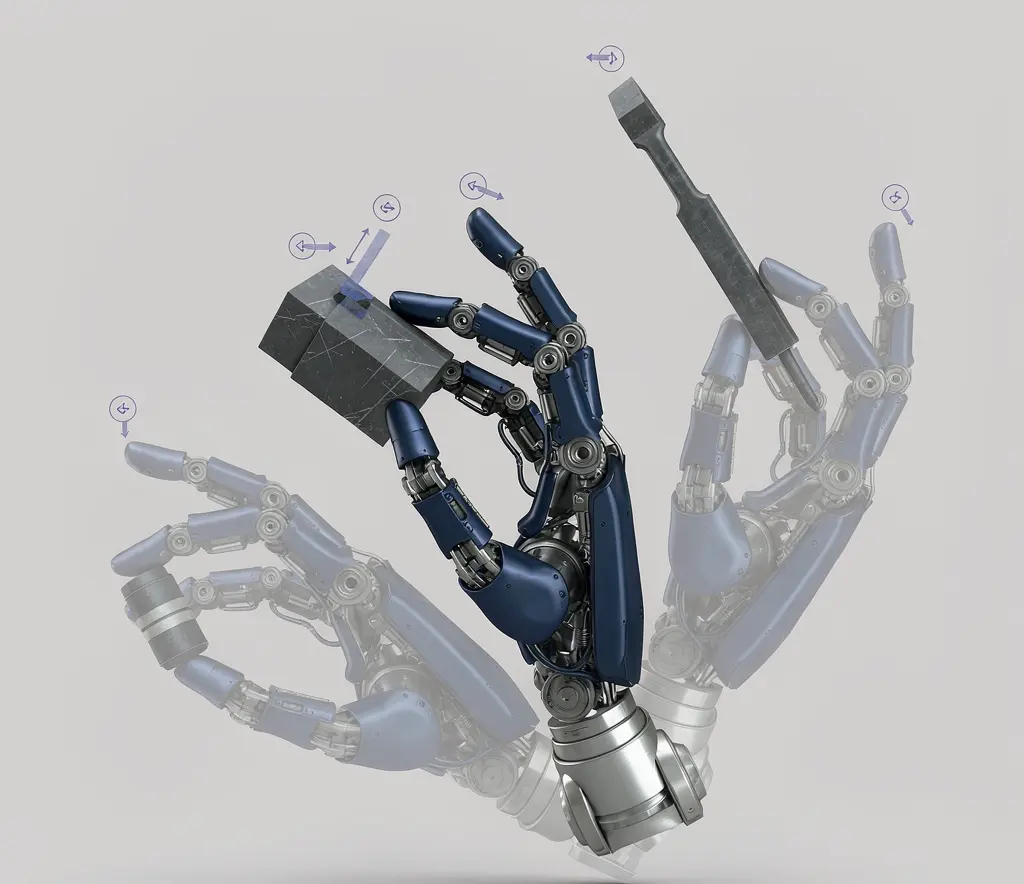
Humanoid Robot Hand Dexterity Verification: Grasp Set, Tool Use, Force Control, and Recovery
Oct 08, 2026

Industrial Exoskeleton Fit and Sizing: Anthropometry, Adjustment Time, PPE, and Shared-Device Programs
Oct 08, 2026

Robot Duty Cycle and Thermal Limits: Why Rated Payload and Speed Do Not Guarantee Continuous Operation
Oct 08, 2026

Robot IP Ratings Explained: What IP54, IP65, and IP67 Do — and Do Not — Prove
Oct 08, 2026
The navigation accuracy on an AMR spec sheet is measured under ideal conditions: flat floor, adequate lighting, no dust, no smoke, no reflective surfaces, no dynamic obstacles.
Real factory or warehouse optical environments are rarely ideal. Dust, smoke, glass walls, direct sunlight, welding arc — any one of these can cause navigation sensors to misjudge or fail. Buyers have reported “navigation unreliable, no positioning sustained” messages when floor texture degrades — this is not a device fault but a real manifestation of environmental conditions affecting visual navigation feature loss.
This article focuses on navigation failure modes in adverse optical environments, symptom identification, and acceptance testing methods. It does not cover SLAM basics.
Dust and Smoke: False Obstacles and Feature Loss
Dust impact on navigation sensors:
| Sensor type | Dust effect | Failure symptom |
| 2D LiDAR | Laser scattered by dust → detects “false obstacles” | Robot stops in empty aisle for no reason |
| 3D LiDAR | Same, but 3D scattering is more complex | Speed reduction, path detour |
| Visual SLAM | Lens covered by dust → blurry images | Positioning drift, feature matching failure |
| Texture navigation | Floor texture covered by dust → feature loss | “Navigation unreliable” warning, lost positioning |
| Safety LiDAR | Dust triggers protective field → false stop | Frequent unexplained stops |
Smoke impact: High concentrations of airborne particles or smoke can degrade optical sensing performance; the degree of degradation depends on sensor type, wavelength, filtering, installation, and concentration, so the actual system must be tested under representative conditions.
Mitigation strategies:
- Periodic sensor cleaning — frequency depends on dust concentration.
- Path planning to avoid high-dust areas — if possible.
- Multi-sensor fusion — degradation behavior is system-specific; verify what happens when input quality degrades.
- Speed reduction — lower speed increases reaction time.
If your environment has dust or smoke (near cutting, grinding, welding operations), ask the supplier to run navigation tests under these conditions.
Glass, Mirrors, and Reflective Metal
Reflective surface impact on navigation sensors:
| Sensor type | Reflection effect | Failure symptom |
| LiDAR | Laser reflected by mirror surface in another direction → detects “ghost obstacles” or loses return signal | Unexplained stops near glass walls or positioning loss |
| Visual SLAM | Mirror creates false features → map errors | Positioning drift, path deviation |
| Safety LiDAR | Reflection triggers protective field → false stop | Frequent stops near glass doors |
Buyers have reported laser navigation failures near glass walls — false detection points prevent the robot from passing normally.
Mitigation strategies:
- Path planning to avoid glass and mirrors — if possible.
- Apply opaque markers on glass — provide trackable features for visual sensors.
- Multi-sensor fusion — degradation behavior is system-specific; verify with the supplier what happens when one sensing modality degrades.
If your route has glass doors, mirrors, or large reflective metal surfaces (stainless steel equipment), ask the supplier to run navigation tests under these conditions.
Direct Sunlight, Shadows, and Welding Arc
Strong light impact on navigation sensors:
| Sensor type | Strong light effect | Failure symptom |
| LiDAR | Sunlight IR component interferes with receiver → SNR drops | Detection range shortened, accuracy drops |
| Visual SLAM | Strong light causes overexposure → image features lost | Positioning drift, feature matching failure |
| Safety LiDAR | Strong light interferes with safety detection → may miss | Safety function degraded |
| Ultrasonics | Not affected by lighting | — |
Shadow impact: Shadow boundaries cause visual feature discontinuities — the robot may lose positioning at the sun/shade boundary.
Welding arc: The high-intensity arc in welding areas contains strong UV and visible light — within close range of welding stations, the intense arc may degrade optical sensor performance. If the AMR route passes near welding stations, verify the sensing architecture and site conditions with the supplier.
Mitigation strategies:
- Direct sunlight areas: Select a sensing architecture qualified for the environment — verify with the supplier what sensing options are available for high-ambient-light conditions.
- Shadow boundaries: Mark these zones in path planning, reduce speed through them.
- Welding areas: Verify the sensing architecture and site conditions with the supplier; any route restrictions must follow the site safety and process plan.
- Outdoor or semi-outdoor routes: Consider sun direction and time-of-day effects.
If your route has direct sunlight (near windows or outdoor sections) or welding operations, ask the supplier to run navigation tests under these conditions.
Repetitive Geometry and Low-Feature Areas
Low-feature areas: Long corridors, large white walls, repetitive shelf rows — these areas lack trackable features, and navigation sensors may “get lost.”
Impact:
- LiDAR SLAM: All scan points look similar → cannot distinguish position → positioning drift.
- Visual SLAM: Image features repeat → feature matching errors → jump to wrong position.
- QR code / marker navigation: Does not rely on environmental features → unaffected.
Mitigation strategies:
- Add reference markers in low-feature areas (reflectors, QR codes, feature patterns).
- Multi-sensor fusion — IMU can maintain positioning for short periods.
- Mark low-feature zones in path planning, reduce speed through them.
If your warehouse has long corridors or repetitive shelf rows, confirm the navigation solution’s positioning reliability in low-feature areas.
A critical distinction: safety sensors (safety LiDAR, safety light curtains, e-stops) and navigation sensors (2D/3D LiDAR, cameras, IMU) are separate systems with different purposes. Adverse optical environments affect both, but the consequences differ — navigation sensor failure causes operational impact (lost positioning), while safety sensor failure causes safety impact (false stop or missed detection).
Any protective-field or safety function adjustment must follow the manufacturer’s procedure and the site safety validation. This article does not provide safety sensor design or configuration advice — safety function selection, verification, and adjustment are covered in the dedicated safety sensing article.
Sensor Fusion and Graceful Degradation
The above are single-sensor failure modes, but real systems use multiple sensors in coordination — understanding fusion and degradation strategies is key to evaluating navigation robustness.
Multi-sensor fusion is not “more sensors = safer” — fusion behavior is system-specific. Verify what happens when input quality degrades: does the system reduce speed, switch to a different sensing mode, or stop? The specific degradation logic depends on the system’s software architecture and configuration.
Fusion strategies:
| Fusion scheme | Primary sensor | Backup sensor | Degradation behavior |
| LiDAR + vision | LiDAR SLAM | Visual SLAM | Degradation behavior is system-specific; verify with the supplier |
| LiDAR + IMU | LiDAR SLAM | IMU dead reckoning | Degradation behavior is system-specific; verify with the supplier |
| Vision + IMU | Visual SLAM | IMU | Degradation behavior is system-specific; verify with the supplier |
| LiDAR + markers | LiDAR SLAM | QR codes / reflectors | Degradation behavior is system-specific; verify with the supplier |
Graceful degradation: The system may reduce performance when a sensor’s input quality degrades — the actual behavior depends on the system’s fusion and degradation logic. This requires degradation logic designed into the software.
Confirm each sensor’s role in the fusion scheme — who is primary, who is backup? How does it degrade on failure? What is the post-degradation performance expectation?
What to Record: Lost Positioning, False Stops, and Manual Recovery
The operational impact of navigation failure is not just “how many mm did accuracy drop” but also these metrics:
| Metric | Why it matters | How to record |
| Lost positioning count/shift | Reflects environmental impact on navigation | System logs |
| False stop count/shift | Reflects sensor misjudgment frequency | System logs |
| Manual recovery count/shift | Reflects system usability without intervention | Operations records |
| Manual recovery time (min/event) | Reflects fault impact duration | Time recording |
| Speed-reduced zone count | Reflects areas needing special handling | Path configuration |
| Speed-reduced zone impact on takt | Reflects efficiency loss | Operations data |
| Environmental condition | Affected sensors | Failure symptom | Mitigation | Acceptance test method |
| Dust | LiDAR/vision/safety LiDAR | False obstacles, feature loss, false stops | Cleaning frequency, multi-sensor fusion, speed reduction | Run in dusty environment, record false stop count |
| Smoke | LiDAR/vision | Detection range shortened, positioning loss | Detour, pause | Test navigation in smoke |
| Glass/mirrors | LiDAR/vision | Ghost obstacles, positioning drift | Apply markers, avoid, multi-sensor | Run near glass walls |
| Direct sunlight | LiDAR/vision | SNR drop, overexposure | Select qualified sensing architecture, shaded path | Test in direct sunlight |
| Shadow boundary | Vision | Feature discontinuity, positioning jump | Mark, reduce speed | Test at shadow boundaries |
| Welding arc | All optical sensors | Possible signal degradation, false detection, or feature loss — verify with the actual sensing architecture and site conditions | Verify sensing architecture and site conditions | Test near welding area |
| Low-feature area | LiDAR/visual SLAM | Positioning drift, position confusion | Add markers, IMU | Test in long corridors/repetitive shelves |
| Floor wear | Texture navigation | Navigation unreliable, lost positioning | Remap, marker backup | Test on worn floor sections |
Dust, smoke, glass, sunlight, welding arc, and low-feature areas can affect different sensing architectures in different ways. We can help define a realistic site test plan.
Please share, if available: route photos or layout, dust or smoke sources, glass or reflective areas, sunlight exposure, welding zones, navigation method, and acceptance criteria.
Review Navigation RisksEnvironmental Test Inputs
- Spec sheet accuracy is under ideal conditions — your environment will almost never fully match.
- Dust, smoke, glass, strong light, and low features are the five navigation killers — each has different failure modes.
- Safety sensing and navigation sensing are separate systems — safety field adjustments are not a navigation tuning exercise and must be done by qualified personnel.
- Sensor fusion behavior is system-specific — verify what happens when input quality degrades, do not assume automatic takeover.
- Safety sensing is a separate concern — any protective-field or safety function adjustment must follow the manufacturer’s procedure and site safety validation.
- Low-feature areas need additional markers — long corridors and repetitive shelves are SLAM blind spots.
- Acceptance is not just about mm — it is about false stops, lost positioning, and manual recovery frequency — these operational metrics reflect real usability.
- Test in adverse optical environments at both FAT and SAT — clean-floor demos cannot replace real-environment verification.
Share on Social:


Contact Us
In This Article
Humanoid Robot Hand Dexterity Verification: Grasp Set, Tool Use, Force Control, and Recovery
Oct 08, 2026
Industrial Exoskeleton Fit and Sizing: Anthropometry, Adjustment Time, PPE, and Shared-Device Programs
Oct 08, 2026
Robot Duty Cycle and Thermal Limits: Why Rated Payload and Speed Do Not Guarantee Continuous Operation
Oct 08, 2026
Robot IP Ratings Explained: What IP54, IP65, and IP67 Do — and Do Not — Prove
Oct 08, 2026