

 Contact Us

 Home /
 Welding Seam Tracking: Touch Sensing vs Through-Arc vs Vision — What Each Method Actually Does
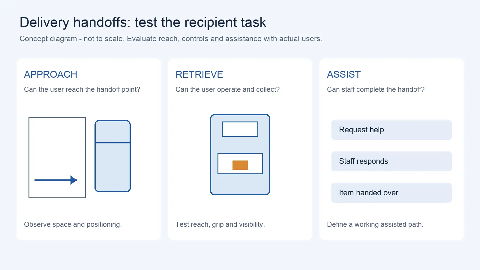
Delivery Robot Accessibility: Tray Reach, Controls, and Assisted Handoffs
Oct 12, 2026
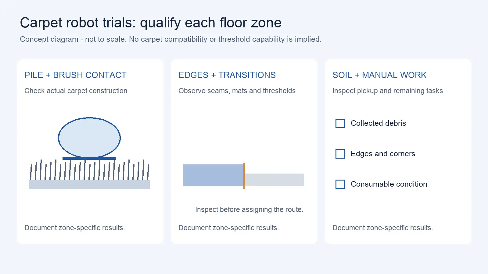
Commercial Carpet-Vacuuming Robots: Pile, Edge Transitions, and Maintenance Limits
Oct 12, 2026
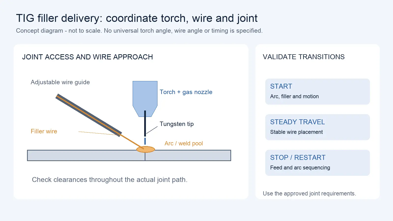
Robotic TIG Filler-Wire Delivery: Feed Angle, Arc Access, and Stop-Start Quality
Oct 12, 2026
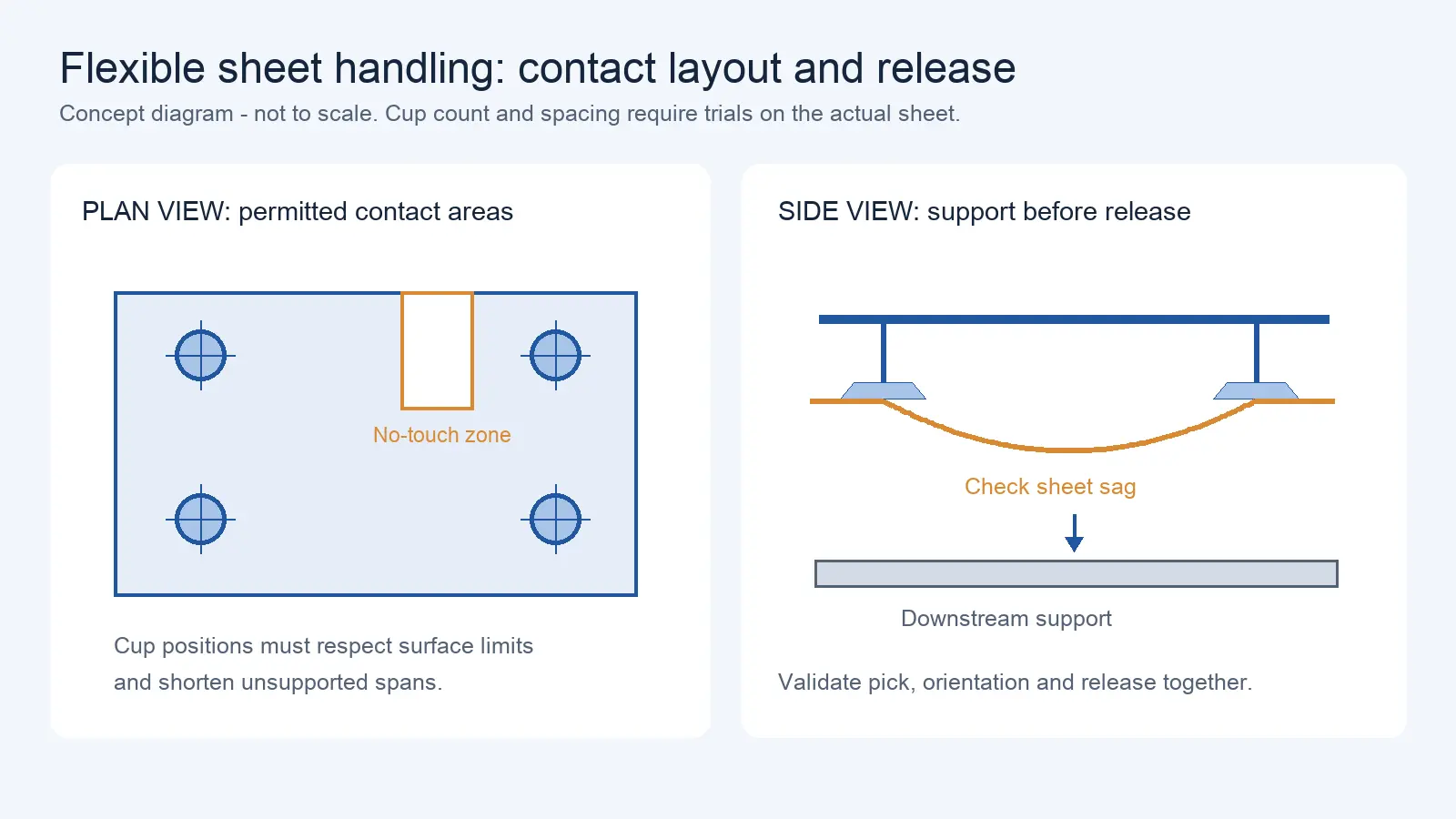
Suction Cup Layout for Flexible Sheets: Sag, Local Stress, and Controlled Release
Oct 12, 2026
Robot welding systems often claim “seam tracking” as a feature. But the three technologies behind that claim — touch sensing, through-arc tracking, and vision-based tracking — do fundamentally different things. Touch sensing finds the seam. Through-arc tracking follows it during welding. Vision can do both, at a higher cost and with different limitations.
This article exists because “seam tracking” is used as a blanket term for three different technologies that do different things — and confusing them leads to buying the wrong system. This article covers touch sensing, through-arc tracking, and vision-based tracking: what each does, what it costs, and which joint conditions favor which method. For welding positioners and external axes, see Article 12.
Seam Finding vs Continuous Seam Tracking: The Fundamental Distinction
Before comparing technologies, understand the two distinct tasks:
Seam finding — locating where the seam starts, its direction, and any major deviations from the programmed path, before welding begins. The robot adjusts its starting position and path based on this information, then welds.
Continuous seam tracking — monitoring the seam position during welding and making real-time corrections to the torch path as the weld progresses. The robot does not know the exact seam path in advance — it follows the seam as it goes, correcting deviation in real time.
A system that does seam finding is not doing seam tracking. A system that does seam tracking may or may not also do seam finding. These are separate capabilities that solve different problems.
| Task | Touch Sensing | Through-Arc Tracking | Vision-Based |
| Seam finding (locate start/path before welding) | Primary method | Arc-on continuous tracking / correction only | Can find seam before welding |
| Continuous tracking (correct during welding) | Not suitable | Primary method — arc-on continuous tracking and correction | Primary method with look-ahead |
Touch Sensing (Wire Contact / Low-Voltage Sensing)
How It Works
The welding wire touches the workpiece surface. A low-voltage circuit closes when the wire contacts the metal, and the controller records the position. By touching at two or more points along the seam, the system can calculate the seam’s actual position and orientation, then offset the programmed path accordingly.
What It Does
- Locates the seam start position
- Detects lateral deviation of the joint from the programmed path
- Measures joint gap or mismatch at discrete points
- Corrects the welding path before the arc starts
What It Does Not Do
- Does not track the seam during welding — it only checks before the arc starts
- Cannot detect mid-weld deviations that develop as heat distortion moves the joint
- Cannot correct for real-time changes in the weld pool position
Cost and Complexity
Touch sensing uses the existing welding wire as the sensor — no additional hardware is required on most robot welding systems. It is the lowest-cost method and is often included as a standard feature in welding robot controllers.
Cycle Time Impact
Each touch point adds time to the cycle (move to contact, detect, record, retract). For a long seam with multiple touch points, the cumulative time can be significant. Request the supplier’s stated time per touch point for your specific system.
When touch sensing is sufficient: If your parts have consistent joint geometry with minor positional variation, and thermal distortion during welding is minimal, touch sensing before welding may be all you need. The programmed path, corrected by touch sensing, will track the seam adequately.
Through-Arc Seam Tracking (TAST)
How It Works
Through-arc tracking uses the welding arc itself as the sensor. As the robot weaves the torch across the joint (left-right oscillation), the arc length changes — shorter on the side where the torch is closer to the joint wall, longer on the other side. These changes in arc length produce measurable variations in welding current and voltage. The controller analyzes these variations to determine the seam position and adjusts the torch path in real time.
The feedback variable — whether the system uses current, voltage, or a combination — depends on the weld power source’s control philosophy. Different power sources (constant voltage vs constant current) produce different signal characteristics, and the tracking algorithm must be matched to the power source type.
What It Does
- Tracks the seam continuously during welding
- Corrects for real-time joint deviation caused by thermal distortion, part variation, or fixture movement
- Requires no additional sensors — the arc is the sensor
- Works on fillet joints, lap joints, and V-grooves where weaving is part of the weld process
What It Does Not Do
- Cannot find the seam before welding — it only works while the arc is on
- Requires torch weaving — if your weld process does not include weaving, through-arc tracking cannot function
- Limited to joints where the arc signal variation is detectable — very thin sheet or joints with minimal geometry may not produce usable signals
- Cannot handle joints where the gap changes significantly mid-weld — the signal interpretation assumes relatively consistent joint geometry
Cost and Complexity
Through-arc tracking is a software/controller feature — no additional hardware is needed beyond the welding power source and torch. It is widely available as an option on robot welding controllers. Industry sources describe through-arc tracking as a widely applied and cost-effective seam tracking solution.
Cycle Time Impact
Through-arc tracking requires torch weaving, which is already part of many welding processes. If weaving is added solely for tracking (not for weld metallurgical reasons), it can add to weld time depending on weave amplitude and frequency.
Material and Joint Geometry Limitations
- Fillet joints: Good signal — the vertical and horizontal surfaces create clear arc length differences during weaving
- V-groove joints: Good signal — the groove walls create measurable variation
- Butt joints (thin sheet): Poor signal — minimal joint geometry to create arc length variation; gap may be too narrow for weaving
- Lap joints: Moderate signal — depends on overlap distance and material thickness
Vision-Based Seam Tracking
How It Works
A camera (typically laser-based structured light or CCD) is mounted on or near the torch. The camera captures an image of the seam ahead of the welding point (look-ahead distance varies by system). Image processing extracts the seam profile — joint geometry, gap, mismatch — and the controller adjusts the torch path and welding parameters in real time.
What It Does
- Both seam finding (before welding) and continuous tracking (during welding)
- Look-ahead tracking — the camera sees the seam before the torch reaches it, allowing the controller to pre-plan corrections
- Handles complex joint geometries — multi-pass welds, varying gap, variable bevel angles
- Can measure joint dimensions (gap, mismatch, bevel angle) and adjust welding parameters (wire feed speed, travel speed, weave amplitude) accordingly
What It Does Not Do
- Cannot see through arc light without specialized optical filtering — arc light is intense and broadband, and it can saturate the camera sensor
- May struggle with highly reflective surfaces (stainless steel, aluminum) — surface reflections can confuse the image processing
- Cannot function if the seam is obscured by spatter, slag, or fumes at the look-ahead distance
Cost and Complexity
Vision-based tracking requires:
- A camera or laser sensor mounted on the torch (hardware cost)
- Image processing software (software license)
- Optical filters to block arc light (integration cost)
- Calibration of the camera-to-torch offset (setup cost)
This is the most expensive of the three methods — the cost premium over through-arc tracking depends on the system complexity and sensor type.
Cycle Time Impact
Vision processing adds minimal cycle time for tracking (the camera runs in parallel with welding), but seam finding with vision adds time depending on the seam length and processing speed. The look-ahead distance means corrections are pre-planned, not reactive — this can improve weld quality compared to reactive through-arc tracking.
Technology Comparison Table
| Dimension | Touch Sensing | Through-Arc Tracking | Vision-Based Tracking |
| Primary function | Seam finding | Continuous tracking | Both (finding + tracking) |
| When it works | Before welding | During welding | Before and during welding |
| Additional hardware | None (uses welding wire) | None (uses welding arc) | Camera/laser + filters + mount |
| Cost | Lowest | Low (software feature) | Highest |
| Joint types | Any (contact-based) | Fillet, V-groove, lap | Most joints (depends on visibility) |
| Thin sheet | ✓ Works | ✗ Limited signal | ✓ Works (if visible) |
| Reflective surfaces (Al, SS) | ✓ Works | ✓ Works | ✗ May struggle |
| Real-time correction | ✗ No | ✓ Yes | ✓ Yes (look-ahead) |
| Weaving required | ✗ No | ✓ Yes | ✗ No |
| Gap/mismatch measurement | ✓ At touch points | ✗ Indirect | ✓ Yes (direct measurement) |
| Multi-parameter adjustment | ✗ No | ✗ Limited | ✓ Yes (gap, angle, mismatch) |
Variation-to-Method Matrix
| Joint Variation | Recommended Method | Why |
| Consistent parts, minor positional deviation | Touch sensing | Low cost; deviation is within pre-weld correction range |
| Thermal distortion during welding (joint moves) | Through-arc or vision | Must correct in real time; touch sensing cannot help mid-weld |
| Variable gap (changes along seam) | Vision | Gap measurement allows wire feed/travel speed adjustment per segment |
| Thin sheet butt joints | Touch sensing or vision | Through-arc signal may be too weak; touch sensing can locate; vision can track |
| Fillet welds on structural steel | Through-arc | Good signal; weaving is standard practice; cost-effective |
| Multi-pass V-groove welds | Vision | Must measure groove geometry per pass; adjust parameters accordingly |
| Aluminum/stainless reflective surfaces | Touch sensing or through-arc | Vision may struggle with reflections; arc and contact methods are unaffected |
| Large parts with fixture variation | Vision | Look-ahead detects fixture-induced deviation; adjusts before torch arrives |
Buyer Verification Checklist
Before purchasing a seam tracking system, verify:
- Whether you need seam finding, continuous tracking, or both
- Joint types at your facility (fillet, butt, lap, V-groove) — and which method handles each
- Material types (carbon steel, stainless, aluminum) — vision may struggle with reflective materials
- Sheet thickness range — through-arc signal quality depends on joint geometry
- Whether your weld process includes torch weaving (required for through-arc tracking)
- Thermal distortion level — does the joint move during welding? (If yes, touch sensing alone is insufficient)
- Gap variation tolerance — if gap varies significantly, can the system adjust welding parameters?
- Cycle time budget — how many seconds can seam finding/tracking add?
- Whether the system can find the seam before welding (touch sensing or vision) or only during welding (through-arc)
- Arc light filtering solution for vision systems — how does it handle the specific arc spectrum of your weld process?
- Camera mounting — is the camera torch-mounted or fixed? Torch-mounted moves with the robot; fixed has a limited field of view
- Calibration frequency — how often must the camera-to-torch offset be recalibrated?
Illustrative Scenario: The Wrong Method for the Wrong Joint
A fabricator welding structural steel fillet joints purchased a vision-based seam tracking system because it was described as “the most advanced” option. The joints were standard T-fillet welds on carbon steel, 6–10 mm throat thickness, with moderate thermal distortion. The parts were fixture-held with ±2–3 mm positional variation.
Analysis after six months showed that the vision system was adding 8–12 seconds (illustrative) per seam for image processing and was occasionally losing track when spatter obscured the look-ahead zone. The fabricator’s neighboring competitor used through-arc tracking on the same type of joints — no additional hardware, no image processing delay, and the weaving required for through-arc tracking was already part of their standard weld process. The through-arc system cost roughly one-third of the vision system (illustrative) and produced equivalent weld quality for this application.
The vision system would have been justified if the joints had variable gaps requiring parameter adjustment, or if the parts had complex geometry that through-arc tracking could not follow. For standard fillet welds with moderate variation, it was overkill.
This is an illustrative scenario based on common welding automation procurement patterns. Actual performance depends on joint geometry, material, and system configuration.
Request a Quote or Technical Evaluation
Tell us what you need the robot to do. Even if some technical details are not yet confirmed, our team can help evaluate suitable options.
Please share, if available: application, key requirements, site and integration conditions, quantity, destination, and target timeline.
Send Your RequirementsRelated Articles
This article covers welding seam tracking technology selection. For welding positioners and external axes, see Article 12. For 2D vs 3D vision system selection (which includes vision technology used in seam tracking), see Article 16.
Share on Social:


Contact Us
In This Article
Delivery Robot Accessibility: Tray Reach, Controls, and Assisted Handoffs
Oct 12, 2026
Commercial Carpet-Vacuuming Robots: Pile, Edge Transitions, and Maintenance Limits
Oct 12, 2026
Robotic TIG Filler-Wire Delivery: Feed Angle, Arc Access, and Stop-Start Quality
Oct 12, 2026
Suction Cup Layout for Flexible Sheets: Sag, Local Stress, and Controlled Release
Oct 12, 2026