

 Contact Us

 Home /
 2D vs 3D Robot Vision: Matching the Vision System to the Task

Central Vacuum Pump vs On-Tool Ejector: Choosing the Vacuum Source for Robotic Picking
Oct 11, 2026

AMR Tugger Tow Capacity: Drawbar Pull, Cart Resistance, and Starting Loads
Oct 11, 2026
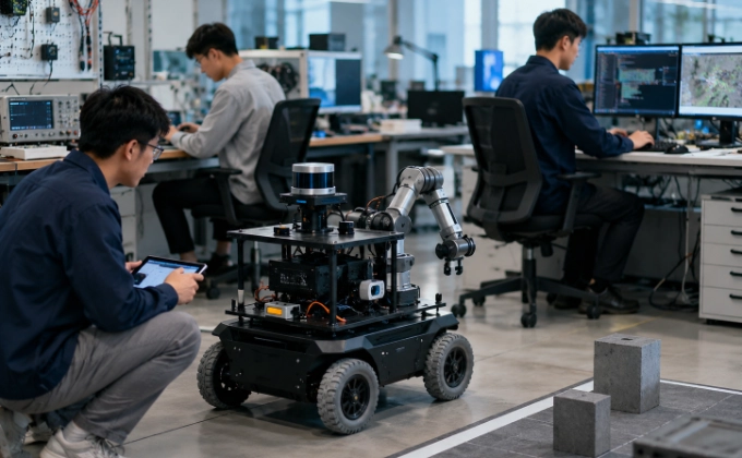
Robotics Teaching Labs: Specify the Student Exercises Before Choosing the Hardware
Oct 11, 2026

SCARA, Delta, or Six-Axis Robot: Choose by Motion, Orientation, and Work Envelope
Oct 11, 2026
Robot vision is not one technology — it is a category that spans from simple presence detection to full 3D bin picking. The gap between what a 2D system can do and what a 3D system can do is not incremental. It is categorical. A 2D system cannot extract depth information, no matter how high its resolution is. A 3D system adds depth, but at higher cost, slower processing, and with its own set of limitations.
This article exists because 2D and 3D vision are often treated as points on a spectrum (more resolution = better) when they are fundamentally different categories. A 12-megapixel 2D camera cannot measure stack height; no amount of 2D resolution solves a 3D problem. This article helps buyers determine which category their application requires. For pallet-specific detection challenges in autonomous forklift docking, see Article 11. For welding seam tracking vision technology, see Article 15.
What 2D Vision Can and Cannot Do
2D Vision Capabilities
A 2D vision system captures a flat image — like a photograph — and processes it to extract information about what is in the image. It can perform:
- Presence/absence detection — is a part there or not?
- Position and orientation (in-plane) — where is the part in the 2D image plane, and which way is it rotated (around the Z-axis)?
- Pattern matching — does the part match a reference template?
- Barcode and QR code reading
- Label inspection — is the label present, correct, and readable?
- Color sorting — which color is the part? (requires color camera)
- Edge and dimension inspection — measuring features that are visible in the 2D image
These capabilities are sufficient for a wide range of industrial tasks. If your application needs to verify that a part is present, check its orientation on a conveyor, read a barcode, or inspect a label — 2D vision is the right tool.
2D Vision Limitations
A 2D system cannot:
- Directly measure height or depth — a conventional 2D image is a projection; it does not directly contain Z-axis information. In some applications, 3D pose can be inferred from known geometry and camera calibration, but this is different from directly sensing depth.
- Directly estimate 6-DOF pose without additional information — full 3D position and orientation (X, Y, Z, roll, pitch, yaw) generally requires depth. Some applications can infer 3D pose from a 2D image using known geometry, camera calibration, and model-based pose estimation (e.g., PnP), but this is not the same as direct depth measurement.
- Reliably perform random 3D bin picking — random 3D bin picking generally requires depth information or another way to infer 3D geometry; a conventional 2D-only approach is usually insufficient for unconstrained piles
- Measure stack height — how many layers are on a pallet, or how tall a stack of sheets is
- Detect 3D surface features — dents, depressions, or surface curvature that are not visible as 2D edges
Key point: A 12-megapixel 2D camera has higher resolution than most 3D systems, but it still cannot tell you how tall a stack of parts is. Resolution and dimensionality are different limitations. Do not upgrade 2D resolution to solve a 3D problem.
3D Vision Technologies: Four Approaches
Structured Light
A projector casts a known pattern (typically a grid or fringe pattern) onto the object. A camera, offset from the projector, captures the deformed pattern. The deformation encodes depth information — the system triangulates each point’s 3D position from the pattern distortion.
Strengths: High accuracy (sub-millimeter in optimal conditions); fast single-shot capture; well-suited to stationary parts.
Limitations: Sensitive to reflective and dark surfaces — the projected pattern bounces off shiny metal or absorbs into dark materials, producing incomplete or noisy point clouds. Requires a projector, which adds cost and can be affected by ambient light.
Stereo Vision
Two cameras are mounted at a known separation distance. The system finds corresponding features in both images and triangulates depth from the parallax (the difference in feature position between the two cameras).
Strengths: Passive — no projector needed; works with natural ambient light; can be compact (two small cameras).
Limitations: Requires texture or features on the object surface — a flat, featureless surface (like a smooth metal sheet) has no features for the stereo matching algorithm to find, producing sparse or inaccurate depth data. Lower accuracy than structured light in most conditions.
Time-of-Flight (ToF)
A light source (typically infrared) emits a pulse, and a sensor measures the time for the reflected light to return. Distance is calculated from the round-trip time. Each pixel in the ToF sensor corresponds to a distance measurement.
Strengths: Works in most lighting conditions — the IR light source is active, so it functions in darkness or dim ambient light. Good for medium-range depth sensing (0.5–5 m). No texture requirement — works on featureless surfaces. Strong direct sunlight containing IR may interfere with ToF sensors — verify under actual deployment conditions.
Limitations: Lower resolution than structured light or stereo — ToF sensors typically have lower pixel counts (e.g., 320×240 or 640×480, manufacturer-stated typical values). Multi-path interference (light bouncing off multiple surfaces before returning) can cause errors, especially in corners or near reflective surfaces.
Laser Triangulation
A laser line (or point) is projected onto the object, and a camera at a known angle captures the line. The position of the line in the camera image encodes the height of the object at that point. The laser sweeps across the object to build a complete 3D profile.
Strengths: Very high precision (sub-0.1 mm in optimal conditions); well-suited to precision measurement and inspection.
Limitations: Line-by-line scanning is slower than single-shot methods (structured light, ToF). Sensitive to surface reflectivity — very shiny surfaces can produce secondary reflections that confuse the measurement.
2D/3D Comparison Table
| Dimension | 2D Vision | 3D Vision |
| Depth information | No | Yes |
| Pose estimation | 2D (X, Y, rotation) | 6-DOF (X, Y, Z, roll, pitch, yaw) |
| Bin picking | Usually insufficient for unconstrained piles | Generally requires depth information |
| Stack height measurement | Not possible without depth | Possible |
| Surface defect detection | Limited (visible edges only) | ✓ Full surface profile |
| Processing speed | Fast (milliseconds) | Slower (100ms to seconds, depending on method) |
| Cost | Low to medium | Medium to high |
| Lighting sensitivity | High (depends on illumination) | Varies by technology |
| Reflective surface handling | N/A (2D projection) | Challenging for structured light and laser; better for ToF |
| Typical applications | Inspection, sorting, barcode, presence | Bin picking, pallet detection, 3D measurement, robot guidance |
3D Technology Comparison
| Technology | Accuracy | Speed | Reflective Surface | Dark Surface | Cost | Best For |
| Structured light | High (varies by working distance, FOV, surface) | Fast (single shot) | Poor | Poor | Medium-High | Stationary parts, inspection |
| Stereo vision | Medium (varies by baseline, texture, distance) | Medium | Poor (needs texture) | Poor (needs texture) | Medium | Natural light, textured surfaces |
| Time-of-Flight (ToF) | Medium (varies by distance, ambient IR) | Fast (single shot) | Moderate (less affected than structured light) | Good (active IR) | Medium | Variable lighting, medium range |
| Laser triangulation | Very high (varies by distance, surface, scan rate) | Slow (line scan) | Moderate | Good | High | Precision measurement, profiling |
Accuracy depends on working distance, field of view, surface properties, ambient lighting, calibration quality, and processing algorithm. Do not compare accuracy values across different technologies without controlling for these variables. Request accuracy data measured at your specific working distance and surface conditions.
Task-to-Vision Matrix
| Task | 2D Sufficient? | 3D Required? | Recommended Technology | Why |
| Part presence on conveyor | ✓ | 2D | Simple detection; no depth needed | |
| Part orientation (in-plane rotation) | ✓ | 2D | Rotation visible in 2D image | |
| Barcode/QR reading | ✓ | 2D | Standard 2D application | |
| Label inspection | ✓ | 2D | Text and graphics are 2D features | |
| Color sorting | ✓ | 2D (color) | Color is a 2D property | |
| Bin picking (random orientation) | ✓ | Structured light or stereo | Must know 3D position and orientation | |
| Pallet detection and mapping | ✓ | ToF or structured light | Must measure pallet height and load geometry | |
| Stack height measurement | ✓ | ToF or laser | Must measure Z-axis dimension | |
| Surface flatness inspection | ✓ | Laser triangulation | Must profile surface in 3D | |
| Robot guidance (part localization) | ✓ (if parts are flat) | ✓ (if parts are 3D) | Depends on part geometry | 2D for flat parts on known plane; 3D for 3D parts |
| Gap and mismatch measurement (welding) | ✓ | Laser triangulation | Must measure cross-section profile | |
| Parcel box detection on pallet | ✓ | ToF (IEEE IRC 2020) | Works in variable lighting; medium accuracy sufficient |
Lighting and Reflectivity: The #1 Practical Issue
Lighting is the most common cause of vision system problems in production. Both 2D and 3D systems are affected, but the failure modes differ:
2D Lighting Issues
- Insufficient light — image too dark for processing; features not visible
- Excessive light — specular reflections (glare) saturate the sensor; features obscured
- Inconsistent light — variations between shifts (daylight through windows vs night) cause different processing results
- Shadows — features in shadow may not be detected; racking shadows on conveyor lines
3D Lighting Issues
- Reflective surfaces — structured light and laser systems produce incomplete or noisy data on shiny metal (stainless steel, aluminum, chrome)
- Dark surfaces — structured light and laser may not produce enough reflected signal; ToF (active IR) is less affected
- Transparent/semi-transparent materials — all 3D methods struggle; light passes through or refracts unpredictably
- Ambient IR — sunlight through windows contains IR that can interfere with ToF sensors
What to Specify in an RFQ
When requesting a vision system, specify:
- Surface material and finish of the parts (matte, glossy, metal, plastic)
- Color range of the parts
- Lighting conditions at the deployment location (lux level, type of lighting, daylight exposure)
- Worst-case lighting scenario (shadows, end-of-day, seasonal variation)
- Whether lighting can be controlled (can you add dedicated lighting? or must the system work with existing facility lighting?)
Calibration: “One-Click” Is a Claim, Not a Guarantee
Some vision system suppliers offer “one-click auto-calibration” to robot manufacturers. This is a valuable feature — it reduces setup time and simplifies commissioning. But it is not a guarantee that calibration is unnecessary or that the calibration will be correct in all conditions.
Calibration establishes the relationship between the camera’s coordinate system and the robot’s coordinate system. If this relationship is wrong, the robot will reach for a position that does not match what the camera sees — resulting in missed picks, collisions, or placement errors.
What “one-click” typically does:
- Automatically identifies a reference pattern or target
- Computes the camera-to-robot transformation matrix
- Stores the calibration for subsequent use
What it does not do:
- Compensate for mechanical changes after calibration (robot mounting shift, camera mount loosening, thermal expansion)
- Handle changes in the optical path (lens contamination, lighting angle change)
- Verify that the calibration is correct for all positions in the workspace (calibration is typically done at one position; accuracy may degrade at the workspace edges)
Buyer note: After any maintenance event that touches the camera mount, robot mounting, or end-effector, recalibrate. After any collision, recalibrate. Periodically verify calibration accuracy by commanding the robot to a known reference point and measuring the actual position.
Cycle Time Impact: 3D Is Slower
3D processing is computationally more intensive than 2D. A 2D image can be processed in milliseconds; 3D point cloud processing can take hundreds of milliseconds to seconds, depending on the point cloud size and processing algorithm.
For applications where cycle time is critical (high-speed picking, line-rate inspection), this processing time matters. Specify the acceptable processing time in the RFQ, and verify that the system can meet it with your actual part complexity and point cloud density.
Vision RFQ Checklist
- Task is defined as 2D or 3D (based on whether depth information is needed)
- Part material and surface finish specified (matte, glossy, metal, plastic, transparent)
- Part color range specified
- Lighting conditions at deployment location documented (lux level, type, variability)
- Worst-case lighting scenario described
- Required cycle time per vision operation specified (including processing time)
- Required accuracy specified (mm for 3D, pixels for 2D)
- Whether parts are stationary or moving during image capture
- Calibration method and frequency specified
- Whether “one-click” calibration is available for your robot model
- Field of view requirements (minimum and maximum part size to be captured)
- Working distance specified (distance from camera/sensor to part)
- Environmental conditions (dust, fumes, temperature, vibration)
- IP rating requirement for the camera/sensor enclosure
- Connectivity requirements (PoE, GigE, USB3, proprietary)
Illustrative Scenario: 2D vs 3D for Pallet Detection
A logistics operation needed to detect and localize parcel boxes on pallets for automated depalletizing. The initial proposal was a 2D vision system — it was lower cost and the team assumed that “detecting boxes” was a 2D task.
Testing revealed that the 2D system could detect the presence and in-plane position of boxes, but could not determine the height of each box or the number of layers on the pallet. The depalletizing robot needed to know the Z-position of each box to plan its pick trajectory — without depth information, it could not determine whether to approach from above at 200 mm or 400 mm.
A 3D ToF sensor (as described in IEEE IRC 2020 research on parcel box detection) was added. The ToF sensor worked in the variable lighting of the warehouse (which included dock door areas with mixed natural and fluorescent light) and provided the depth map needed for the robot to plan pick trajectories. The 2D system was retained for barcode reading on each detected box — a task where 2D was sufficient and 3D would have added unnecessary cost and processing time.
This is an illustrative scenario based on common warehouse automation patterns. Actual performance depends on box dimensions, lighting conditions, and system configuration.
Request a Quote or Technical Evaluation
Tell us what you need the robot to do. Even if some technical details are not yet confirmed, our team can help evaluate suitable options.
Please share, if available: application, key requirements, site and integration conditions, quantity, destination, and target timeline.
Send Your RequirementsRelated Articles
This article focuses on 2D vs 3D vision system selection. For pallet-specific detection challenges in autonomous forklift docking, see Article 11. For welding seam tracking vision technology, see Article 15.
Share on Social:


Contact Us
In This Article
Central Vacuum Pump vs On-Tool Ejector: Choosing the Vacuum Source for Robotic Picking
Oct 11, 2026
AMR Tugger Tow Capacity: Drawbar Pull, Cart Resistance, and Starting Loads
Oct 11, 2026
Robotics Teaching Labs: Specify the Student Exercises Before Choosing the Hardware
Oct 11, 2026
SCARA, Delta, or Six-Axis Robot: Choose by Motion, Orientation, and Work Envelope
Oct 11, 2026