

 Contact Us

 Home /
 Robotic TIG Filler-Wire Delivery: Feed Angle, Arc Access, and Stop-Start Quality
Delivery Robot Accessibility: Tray Reach, Controls, and Assisted Handoffs
Oct 12, 2026
Commercial Carpet-Vacuuming Robots: Pile, Edge Transitions, and Maintenance Limits
Oct 12, 2026
Robotic TIG Filler-Wire Delivery: Feed Angle, Arc Access, and Stop-Start Quality
Oct 12, 2026
Suction Cup Layout for Flexible Sheets: Sag, Local Stress, and Controlled Release
Oct 12, 2026
Once TIG has been chosen for a joint, the remaining question is not which process to use but how to deliver the filler wire into the arc reliably. TIG welding with a non-consumable tungsten electrode produces a stable arc and gives excellent control, which is exactly why it is used on critical joints. It also means the wire has to arrive at the right place, at the right angle, at the right moment, because the single electrode does not feed filler by itself. Automating a TIG joint means solving a wire-delivery geometry problem, and that problem looks different at a start, during a long run, and at a stop.
Define the Joint and Filler Requirement
The wire-delivery design starts from the approved welding requirement, not from a preferred setup.
Read the welding procedure for the joint: whether filler is required at all, the filler material and diameter, the joint configuration, the position, and the shielding gas. Some TIG joints are autogenous, meaning they are made without filler, and adding wire would change the result. Others require a specific filler to match the base metal or to control the weld composition.
Do not set these values yourself. The filler material, diameter, and the conditions under which the joint is acceptable belong to the approved procedure, which your welding engineering function owns. The delivery system's job is to place the specified wire where the procedure expects it. If the procedure is not yet written for a new joint, that is an open item to resolve before the robot configuration is fixed.
Coordinate Torch, Wire, and Workpiece Access
With the requirement known, the design checks whether the torch, the wire, and the workpiece can all occupy the space the weld needs.
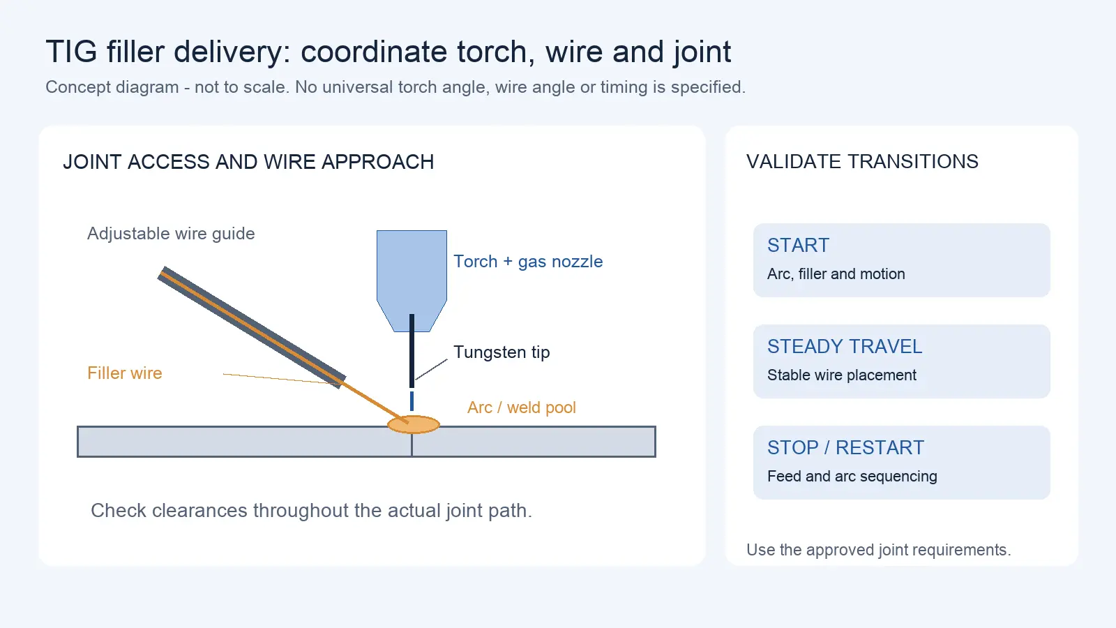
TIG puts three things close together at the joint: the torch with its tungsten electrode and gas nozzle, the wire and its guide, and the workpiece surfaces that form the joint. Each takes space, and in a corner, a narrow groove, or a curved joint, that space runs out. The filler must enter a position in the weld pool appropriate to the approved GTAW procedure and torch orientation; verify the actual guide and torch clearances for each joint and travel direction. The two angles interact, so changing one changes the other.
Documented torch and wire-feed designs address this by making the wire guide adjustable: patents describe a filler-wire guide that can rotate and move axially, with its position adjustable relative to the tungsten tip, and that can be moved aside to change the torch neck. This adjustability exists precisely because the correct wire position depends on the joint. For your application, verify the actual torch, wire guide, and workpiece geometry in the postures the cycle requires, and look for interference at the worst-posture points rather than only at a convenient sample.
Review Wire Position and Feed Consistency
A wire that starts in the right place has to keep arriving consistently through the whole run.
The position of the wire relative to the tungsten tip and the puddle affects where filler enters and whether it melts into the weld or balls up at the tip. Wire-feed studies in related processes show that the feed position and angle have a marked effect, and that poor positioning causes defects such as lack of fusion. Laser filler-wire studies provide a useful hypothesis that wire entry geometry matters, but they do not establish TIG-specific acceptable angles, feed positions, or defect probabilities. Confirm wire behavior and welding quality against TIG-specific equipment documentation and representative GTAW trials. This is the reason wire position is a setting, not an afterthought.
Feed consistency depends on the drive and the guide. Wire-feed patents describe feeding the filler in an accelerate, steady, then decelerate sequence, with parameters set per material and diameter by experiment. That tells you two things: feeding is controlled rather than free-running, and the correct parameters are established by testing rather than by a universal number.
Hot-wire TIG systems may use controlled wire feeding and preheating, but any claimed travel-speed or deposition-rate improvement must identify the exact system, joint, base material, baseline process, and test conditions. The takeaway for a buyer is the same as for a standard feed: feeding is a controlled parameter with a published setting range, and the numbers that matter are the ones confirmed on your procedure and your joint. Ask the supplier for the wire-position accuracy, the guide arrangement, the straightness of the wire path, and how the feed rate is controlled. Where specifics are not published, treat the parameter values as items to confirm against the approved procedure and the equipment documentation, not to assume.
Validate Starts, Stops, and Restarts
Starts, stops, and restarts deserve separate validation because arc energy, filler delivery, and robot motion are changing together and may introduce defects not seen in steady travel.
At a start, the arc must establish, the wire must enter at the right moment, and the motion must begin in step. If the wire arrives early it can chill the arc or stick; if the wire arrives too late for the specified joint and process, it may cause inadequate filler deposition or an unacceptable start condition. At a stop, the wire must retract or stop as the arc tapers, or the end of the weld can build up or sag. On a restart, the system has to re-establish the arc and the wire position on an already-partly-welded joint.
Check these transitions specifically, with the conditions the approved procedure defines. Look at the start and stop of the weld, not only the middle, and look for defects that appear only at transitions: incomplete fusion at the start, a crater or a hump at the stop, a cold restart. The acceptance criteria come from the approved procedure and the applicable code, not from appearance alone. This validation is a welding-function task, done with your welding engineering input.
Handle Curves and Changing Torch Angles
Changing torch posture may also raise the separate question of welding positioners and external axes.
A straight sample weld is the easiest case. A joint that curves, or that requires the torch angle to change, changes where the wire has to be.
On a curved joint, the wire approach that works at one point may not reach the puddle at the next if the torch orientation rotates relative to the joint. On a joint with a changing angle, the torch has to follow the joint while the wire guide keeps its relationship to the puddle, and those two motions can conflict. The result is that a setup verified on a straight plate may not hold on the real part.
Do not extrapolate from a straight sample. Test on joints that curve and on joints where the torch angle changes, and observe whether the wire position holds. Where it drifts, the fix is a programming or fixture question, and it should be resolved against the real geometry rather than assumed away. Record which joint shapes were tested and which were not, so the untested ones stay visible.
If seam-location variation drives the problem rather than filler-wire entry alone, review weld seam finding and tracking methods.
Approve a Joint-Specific Trial
The evidence for a TIG wire-delivery setup is a trial on the actual joint, not a visual check of a bead.
Run the trial across the joint types and torch postures the production cycle will use, and inspect the results for the defects that wire delivery can cause: lack of fusion, poor tie-in, start and stop defects, and porosity. Visual appearance is one input, but it is not the whole quality result; the acceptance criteria come from the approved procedure, which may call for additional inspection for critical joints.
Record, for each joint and posture, the wire position, the feed parameters, and the result. This matrix, joint against torch posture against wire approach against start-stop quality, is the document that shows which combinations are proven and which still need work. Keep the trial tied to the approved procedure so that a passing weld means the procedure was met, not merely that the bead looked acceptable.
Share the joint drawings, approved filler requirements, planned torch poses, wire-guide arrangement and any trial records showing starts, stops and restarts. AIsirRobot can help structure the information for a preliminary application assessment and prepare manufacturer clarification questions.
Share on Social:


Contact Us
In This Article
Delivery Robot Accessibility: Tray Reach, Controls, and Assisted Handoffs
Oct 12, 2026
Commercial Carpet-Vacuuming Robots: Pile, Edge Transitions, and Maintenance Limits
Oct 12, 2026
Robotic TIG Filler-Wire Delivery: Feed Angle, Arc Access, and Stop-Start Quality
Oct 12, 2026
Suction Cup Layout for Flexible Sheets: Sag, Local Stress, and Controlled Release
Oct 12, 2026