

 Contact Us

 Home /
 From Pilot to Multi-Site Rollout: How to Scale a Robot Deployment Across 10, 50, or 100 Locations
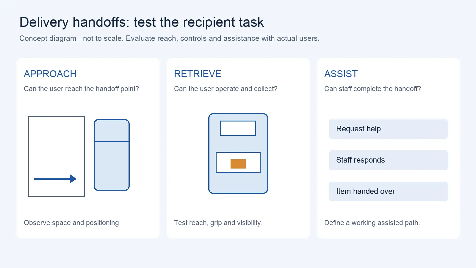
Delivery Robot Accessibility: Tray Reach, Controls, and Assisted Handoffs
Oct 12, 2026
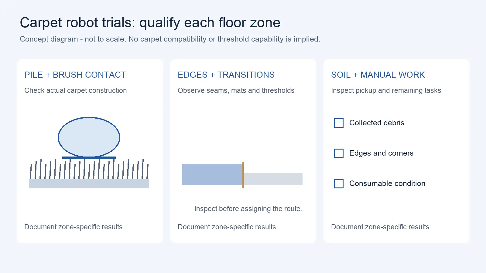
Commercial Carpet-Vacuuming Robots: Pile, Edge Transitions, and Maintenance Limits
Oct 12, 2026
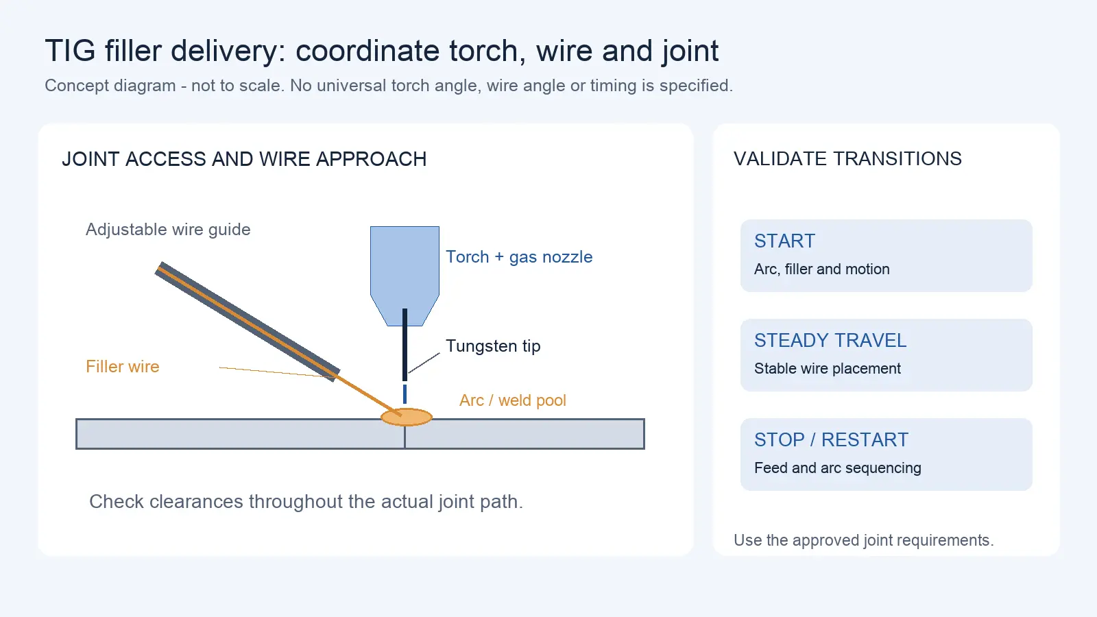
Robotic TIG Filler-Wire Delivery: Feed Angle, Arc Access, and Stop-Start Quality
Oct 12, 2026
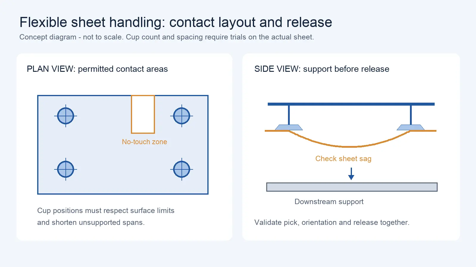
Suction Cup Layout for Flexible Sheets: Sag, Local Stress, and Controlled Release
Oct 12, 2026
A successful pilot at one site does not guarantee a successful rollout across dozens or hundreds of sites. The pilot proves that the robot can perform the task under specific conditions. The rollout requires that the same performance can be replicated across sites that differ in layout, infrastructure, staff, local regulations, and operational priorities. This article explains why pilots do not automatically scale, what the pilot must prove before expansion, and how to structure a phased rollout that manages risk at each stage.
Why a Successful Pilot Does Not Automatically Scale
A pilot succeeds when the robot performs the required task at one site under one set of conditions. Scaling means reproducing that performance at sites that may have different floor plans, different elevator brands, different network infrastructure, different staff skill levels, different local safety regulations, and different operational schedules. The pilot answers the question: “Can this robot do this task?” The rollout answers a different question: “Can this configuration be deployed, operated, and supported at sites we have not yet visited?”
The gap between these two questions is where most multi-site robot projects stall. Common failure patterns include:
- Configuration drift: Each site receives a slightly different configuration because no one documented the pilot configuration precisely enough. After 10 sites, the fleet has 10 variants, and support becomes unmanageable.
- Infrastructure assumptions: The pilot site had good Wi-Fi, adequate power, and a cooperative elevator. Site 7 has Wi-Fi dead zones, a 15-amp circuit shared with other equipment, and an elevator controller from a different manufacturer.
- Staff readiness gap: The pilot site had an enthusiastic champion who learned the system inside out. Sites 3–10 have operators who received 2 hours of training and are expected to manage exceptions they have never seen.
- Support scaling failure: The supplier provided excellent support during the pilot because it was a flagship project. At 20 sites, the same supplier’s response time stretches to days, not hours.
- Cost escalation: The pilot budget covered one robot, one integration, and one set of spares. The rollout budget must cover site preparation, training, spare parts pools, fleet management software, and ongoing support across all locations.
The solution is not to avoid scaling. It is to design the pilot for scalability from the start—and to structure the rollout in phases that surface problems before they multiply.
Define What the Pilot Must Prove Before Expansion
Before authorizing expansion beyond the pilot site, the project team should verify that the pilot has proven the following:
Technical Feasibility
- The robot performs the target task at the required throughput, accuracy, and reliability under real production conditions (not just controlled test conditions)
- The robot integrates with the required systems (WMS, MES, elevator, door, machine) and the integration is stable over a sustained period
- The robot operates safely in the production environment, with a completed risk assessment and documented safety procedures
- The robot’s failure modes are understood: identify observed failure modes and define what remains unknown before rollout. A short pilot may not fully reveal long-term reliability patterns.
Operational Readiness
- Operators have been trained and can run the robot through a full shift without external support
- Documented SOPs cover normal operation, exception handling, and maintenance
- The site has a designated robot owner—someone accountable for the robot’s performance, maintenance, and issue escalation
- Spare parts are on hand, and the replenishment process is defined
Commercial Validation
- The actual project cost has been tracked, including all hidden costs (site preparation, integration, training, travel, spares)
- The actual operational benefit has been measured against the baseline (throughput improvement, labor reduction, quality improvement, or downtime reduction)
- The business case holds at the actual cost and benefit—not just at the estimated cost and projected benefit
Scalability Evidence
- The pilot configuration has been documented in sufficient detail that it can be replicated: robot model, software version, parameter file, map file (for mobile robots), integration configuration, SOPs, training materials, and spare parts list
- The configuration has been tested for adaptability: can the map be updated for a different layout? Can the integration be reconfigured for a different elevator brand? Can the SOP be adapted for a different shift structure?
- The support model has been validated: what happens when the robot faults at 2 AM? Who responds? How fast? What is the escalation path?
If any of these items is missing, the pilot is not ready to scale. Expanding anyway means carrying the same gap into every subsequent site—multiplied by the number of sites.
Standardize the Core Robot Configuration—but Not Every Site Detail
The key to scalable deployment is separating what must be standardized from what must be site-specific. This separation should be made explicitly, documented in a configuration standard, and enforced through the rollout process.
What Should Be Standardized
| Standardized Element | Why |
| Robot model and payload class | Simplifies spare parts, training, and support |
| Controller software version | Ensures consistent behavior and compatibility |
| End-effector type (within a site category) | Reduces spare parts variety and training scope |
| Fleet management platform | Enables multi-site visibility and centralized reporting |
| Safety configuration approach | Ensures consistent safety behavior and audit trail |
| Training curriculum | Ensures all operators receive the same foundation |
| Reporting format | Enables cross-site performance comparison |
| Spare parts list (per site category) | Enables centralized spare parts procurement |
| SOP structure | Ensures consistent exception handling across sites |
| Integration protocol standards | Simplifies IT/OT review and reduces integration engineering per site |
What Should Stay Site-Specific
| Site-Specific Element | Why |
| Site layout and robot map | Every site has a different floor plan |
| Traffic routes and speed zones | Routes depend on site layout and traffic patterns |
| Elevator and door integration | Different sites may have different building systems |
| Network configuration | IP ranges, Wi-Fi coverage, and firewall rules vary by site |
| Floor surface and cleaning schedule | Different sites have different floor materials and maintenance routines |
| Shift structure and operating hours | Sites may have different shift patterns and peak hours |
| Local safety regulations | Different countries or regions may have different safety standards |
| Staff language and training delivery | Training materials may need translation or localization |
| Utility availability | Power, water, drainage, and compressed air vary by site |
The boundary between standardized and site-specific should be defined in a configuration standard document that serves as the template for every new site. This document should specify: “These elements are fixed. These elements are parameterized. These elements are site-specific and must be configured during site preparation.”
Site Readiness Audits Before Each Rollout Wave
Before any site goes live, a site readiness audit should verify that the site meets the minimum requirements for deployment. The audit should cover:
Physical Readiness
- Floor condition: flatness, load capacity, surface material (for mobile robots)
- Space: sufficient area for robot, charging station, and maintenance access
- Utilities: power supply (correct voltage, amperage, dedicated circuit), water and drainage (for cleaning robots), compressed air (if needed)
- Safety infrastructure: guarding, signage, pedestrian separation (if required by risk assessment)
Network Readiness
- Wi-Fi coverage across all robot routes (measured, not assumed)
- Network capacity for the expected number of robots
- Firewall and security configuration for robot-to-cloud or robot-to-WMS communication
- IP address allocation and VLAN configuration
Integration Readiness
- Elevator controller interface available and tested (if applicable)
- Door controller interface available and tested (if applicable)
- WMS/MES integration tested with the site’s specific system version
- Machine interface (CNC, conveyor, press) verified for the robot’s I/O and communication protocol
Staff Readiness
- Operators identified and training scheduled before go-live
- Site robot owner identified and briefed on responsibilities
- Maintenance contact defined (internal or external)
- Escalation path documented: who to call, in what order, for what type of issue
Logistics Readiness
- Robot delivery scheduled and access confirmed (loading dock, freight elevator, clear path to installation point)
- Spare parts delivered to site or regional spares pool
- Installation tools and equipment available
- Commissioning schedule confirmed with supplier or integrator
The audit should produce a checklist with pass/fail or conditional status for each item. Sites that fail the audit should not proceed to installation until the gaps are resolved. This is harder to enforce than it sounds—project pressure often pushes teams to “install and fix later,” which is exactly the approach that creates deployment failures at scale.
Training, SOPs, Local Ownership and Escalation Paths
At scale, the project team cannot be on-site at every location. The success of each site depends on the local team’s ability to operate, maintain, and escalate issues. Three elements make this possible:
Training
- Operator training: covers normal operation, exception handling, and basic maintenance. Should be delivered on-site, in the local language, with hands-on practice on the actual installed robot.
- Technician training: covers preventive maintenance, spare part replacement, and first-line troubleshooting. Should be delivered to designated maintenance staff, not just operators.
- Train-the-trainer: for multi-site rollouts, designate a regional trainer who can deliver operator training at new sites without requiring the original supplier or project team to travel.
SOPs (Standard Operating Procedures)
SOPs should be written for the site-specific configuration, not for a generic robot. Each SOP should cover:
- Normal startup and shutdown
- Normal operation sequence
- Exception handling: robot stopped, robot faulted, robot off-path, payload dropped, network down
- Preventive maintenance tasks and schedule
- Spare part replacement procedures (for designated parts only—more complex replacements should be escalated)
- Emergency stop and recovery
- Escalation: who to contact, what information to provide, what to do while waiting
Local Ownership
Every site needs a designated robot owner—someone who is accountable for the robot’s performance, maintenance schedule, issue escalation, and reporting. Without a local owner, the robot becomes orphaned: no one is responsible when it faults, and no one tracks whether it is meeting its performance targets.
Escalation Paths
The escalation path should be documented and posted at each site:
| Level | Who | Response | Example Issues |
| 1 | Site operator | Self-resolve using SOP | Minor fault, obstacle cleared, battery swap |
| 2 | Site technician | On-site within X hours | Part replacement, configuration adjustment |
| 3 | Regional support | Remote within X hours, on-site within Y hours | Software issue, integration failure, recurring fault |
| 4 | Supplier/integrator | Per SLA | Hardware failure, major integration issue, safety concern |
Spare Parts, Remote Support and Fleet Monitoring at Scale
Spare Parts Strategy
For a single-site pilot, spare parts can be ordered as needed. For a multi-site fleet, the spare parts strategy must be planned:
- Critical spares (parts that cause immediate downtime if failed): maintain at each site or at a regional hub within 24-hour shipping distance
- Wear parts (parts that degrade over time): maintain at each site based on expected replacement frequency
- Consumables (brushes, filters, etc.): maintain at each site based on usage rate
- Long-lead parts (parts with supplier lead time that may affect operations): maintain at a regional hub or central pool
The spare parts list should be defined per site category, not per individual site, to avoid managing dozens of different parts lists.
Remote Support
Remote support capability becomes critical at scale. The project team should verify:
- Can the supplier or integrator connect remotely to the robot for diagnostics?
- What is the remote support response time commitment?
- Is remote support available in the time zone of each site?
- What is the escalation path from remote support to on-site visit?
- Who authorizes remote access, and what are the cybersecurity implications?
Fleet Monitoring
A fleet management platform with multi-site visibility becomes increasingly important as the number of sites grows. Whether and when a platform becomes necessary depends on the scale, criticality, and complexity of the deployment—not on a fixed site-count threshold. The platform should provide:
- Real-time status of every robot across all sites
- Alerting for faults, low battery, off-path events, and downtime
- Utilization and performance reporting by site, by robot, and by fleet
- Centralized configuration management (push configuration updates to multiple sites)
- Role-based access (site operators see their site; regional managers see their region; project team sees all sites)
Phased Rollout: 1 Site → 5 Sites → Regional → Network-Wide
A phased rollout structure manages risk by surfacing problems at each stage before they multiply across the full network.
Phase 1: Pilot (1 Site)
- Deploy and validate the full configuration at one representative site
- Complete the pilot checklist (technical, operational, commercial, scalability)
- Document the configuration standard
- Define the site readiness audit checklist
- Develop and test SOPs and training materials
Phase 2: Early Expansion (5 Sites)
- Deploy at 4 additional sites that represent different site categories (size, layout, building systems, region)
- Test the configuration standard’s adaptability: can it be applied to each site without creating a new variant?
- Test the site readiness audit: does it catch issues before installation?
- Test the training and SOP model: can new operators be trained without the original project team?
- Test the spare parts and support model: does the response meet the SLA at sites that are not the pilot site?
- Refine the configuration standard, audit checklist, and SOPs based on lessons learned
Phase 3: Regional Rollout (All Sites in 1–2 Regions)
- Deploy across all sites in a region (or country)
- Validate the regional support model: spare parts hub, regional trainer, escalation path
- Test the fleet monitoring platform at regional scale: does it handle the number of robots and sites without performance issues?
- Begin collecting cross-site performance data to identify outliers (sites that perform significantly better or worse than average)
- Establish the rhythm of operations: weekly performance review, monthly maintenance audit, quarterly configuration review
Phase 4: Network-Wide Rollout (All Sites)
- Deploy across all remaining sites
- The configuration standard, audit checklist, SOPs, training model, spare parts strategy, and support model should be stable by this phase
- The primary risk at this stage is execution capacity: can the deployment team, supplier, and integrator handle the volume of simultaneous or near-simultaneous deployments?
- Consider parallel deployment waves rather than sequential deployment to manage capacity
Configuration Version Control
The configuration standard should be version-controlled; each site deployment produces lessons that update the standard for the next site. Without version control, the standard drifts as different team members apply ad-hoc changes, and the “standard” becomes a collection of undocumented variants.
A simple status framework can help track configuration maturity:
| Status | Meaning |
| Draft | Initial version, not yet tested at a second site |
| Tested | Validated at 2+ sites with different conditions |
| Stable | Tested across multiple sites and regions; changes require formal change control |
Each configuration element should carry: version number, owner, evidence of validation, and date of last review.
Enterprise Rollout Readiness Checklist
Before authorizing the next rollout phase, verify the following:
| Readiness Dimension | Phase 1→2 | Phase 2→3 | Phase 3→4 |
| Configuration standard documented | Required | Updated | Stable |
| Site readiness audit checklist | Drafted | Tested | Validated |
| SOPs written and tested | Required | Updated | Stable |
| Training materials ready | Required | Updated | Stable |
| Spare parts strategy defined | Draft | Tested | Operational |
| Support model validated (SLA) | At pilot site | At 5 sites | At regional scale |
| Fleet monitoring platform | Selected | Deployed | Multi-site operational |
| Local owner identified per site | Required | Required | Required |
| Escalation path documented | Required | Required | Required |
| Performance baseline established | Required | Cross-site comparison | Regional benchmark |
| Change control process | Drafted | Tested | Enforced |
The checklist is cumulative: each phase builds on the previous one. An item that is “Draft” in Phase 1 must be “Tested” in Phase 2 and “Stable” or “Operational” by Phase 3. Rushing to Phase 4 with items still at “Draft” or “Tested” is a common cause of rollout failure at scale.
For multi-site standardization principles (what to standardize vs. what to keep site-specific), see our Multi-Site Standardization guide. For spare parts planning, see our Spare Parts Planning guide. For fleet management capabilities, see our Robot Fleet Management guide.
Request a Quote or Technical Evaluation
Tell us what you need the robot to do. Even if some technical details are not yet confirmed, our team can help evaluate suitable options.
Please share, if available: application, key requirements, site and integration conditions, quantity, destination, and target timeline.
Send Your RequirementsShare on Social:


Contact Us
In This Article
Delivery Robot Accessibility: Tray Reach, Controls, and Assisted Handoffs
Oct 12, 2026
Commercial Carpet-Vacuuming Robots: Pile, Edge Transitions, and Maintenance Limits
Oct 12, 2026
Robotic TIG Filler-Wire Delivery: Feed Angle, Arc Access, and Stop-Start Quality
Oct 12, 2026
Suction Cup Layout for Flexible Sheets: Sag, Local Stress, and Controlled Release
Oct 12, 2026