

 Contact Us

 Home /
 Automatic Robot Tool Changers: Payload, Lock Confirmation, Utilities, Tool ID, and Parking Stations
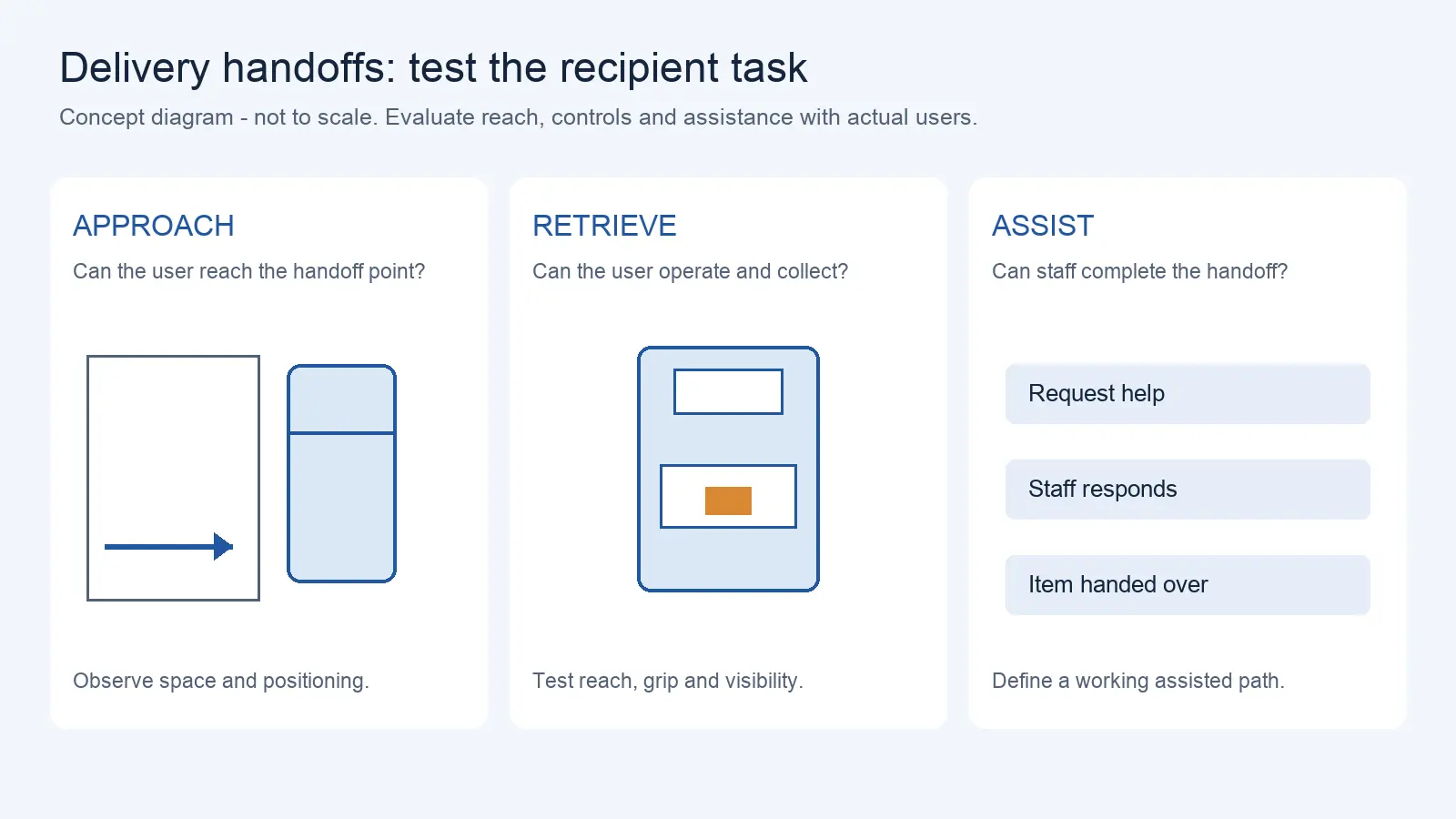
Delivery Robot Accessibility: Tray Reach, Controls, and Assisted Handoffs
Oct 12, 2026
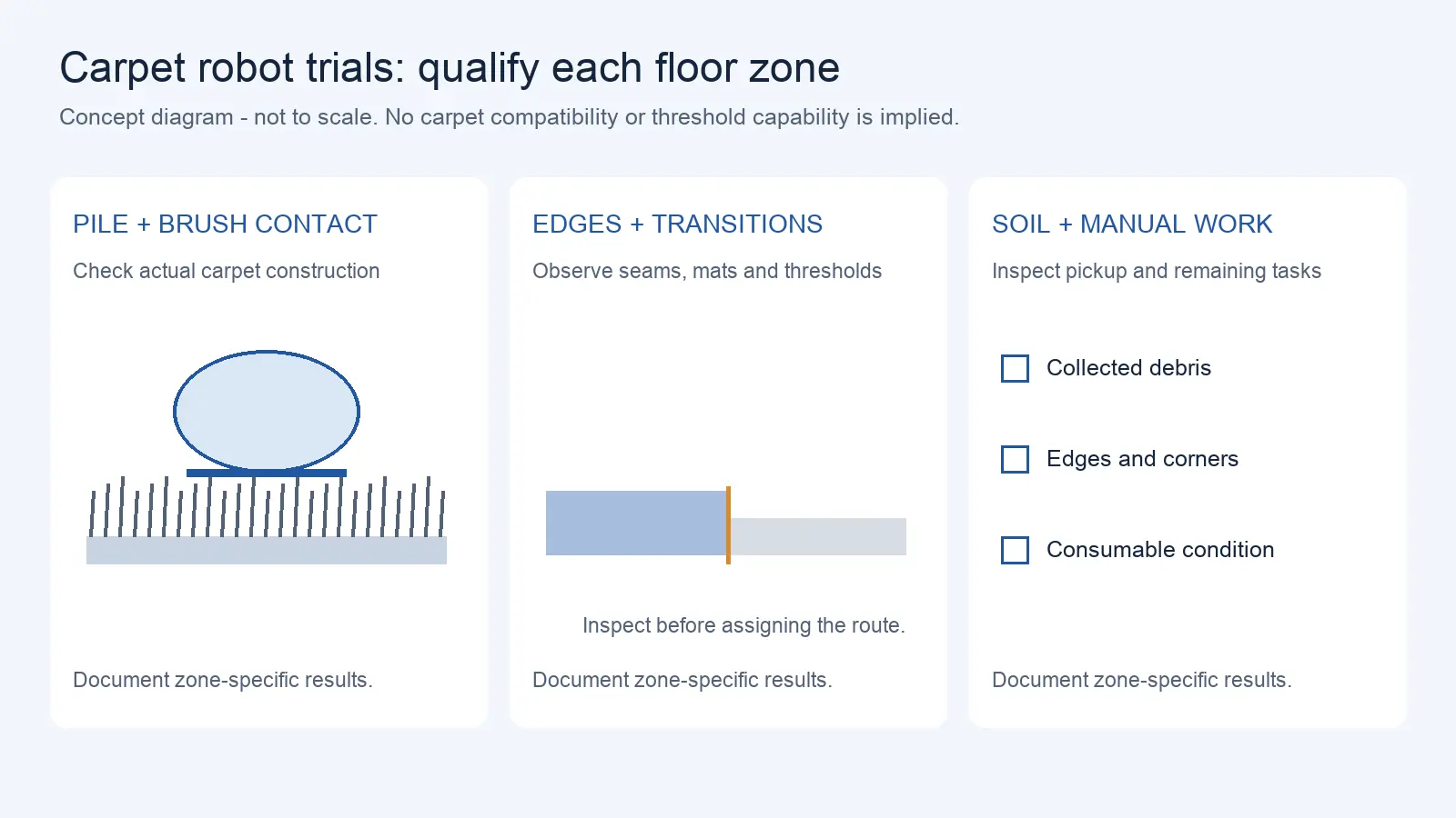
Commercial Carpet-Vacuuming Robots: Pile, Edge Transitions, and Maintenance Limits
Oct 12, 2026
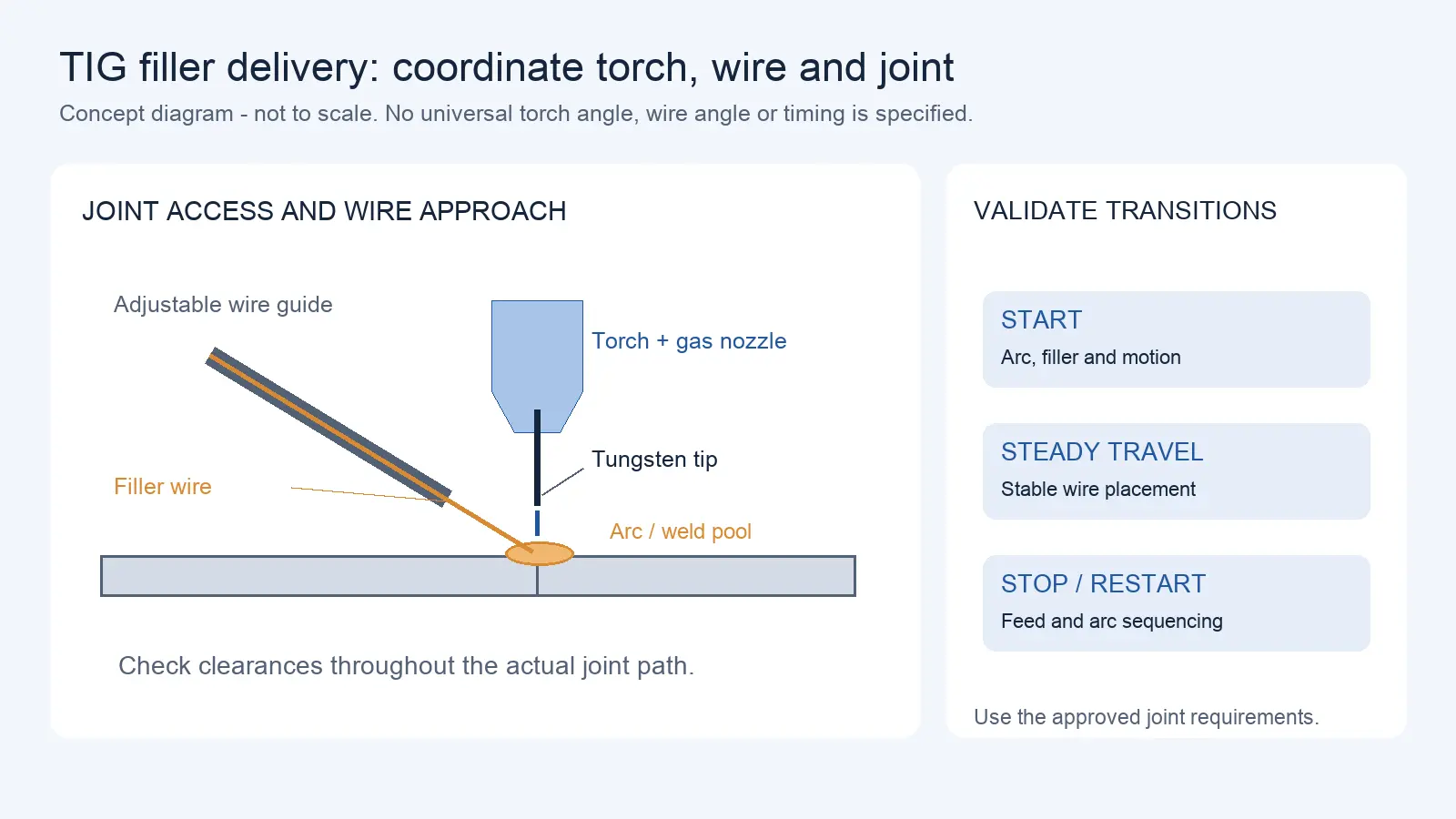
Robotic TIG Filler-Wire Delivery: Feed Angle, Arc Access, and Stop-Start Quality
Oct 12, 2026
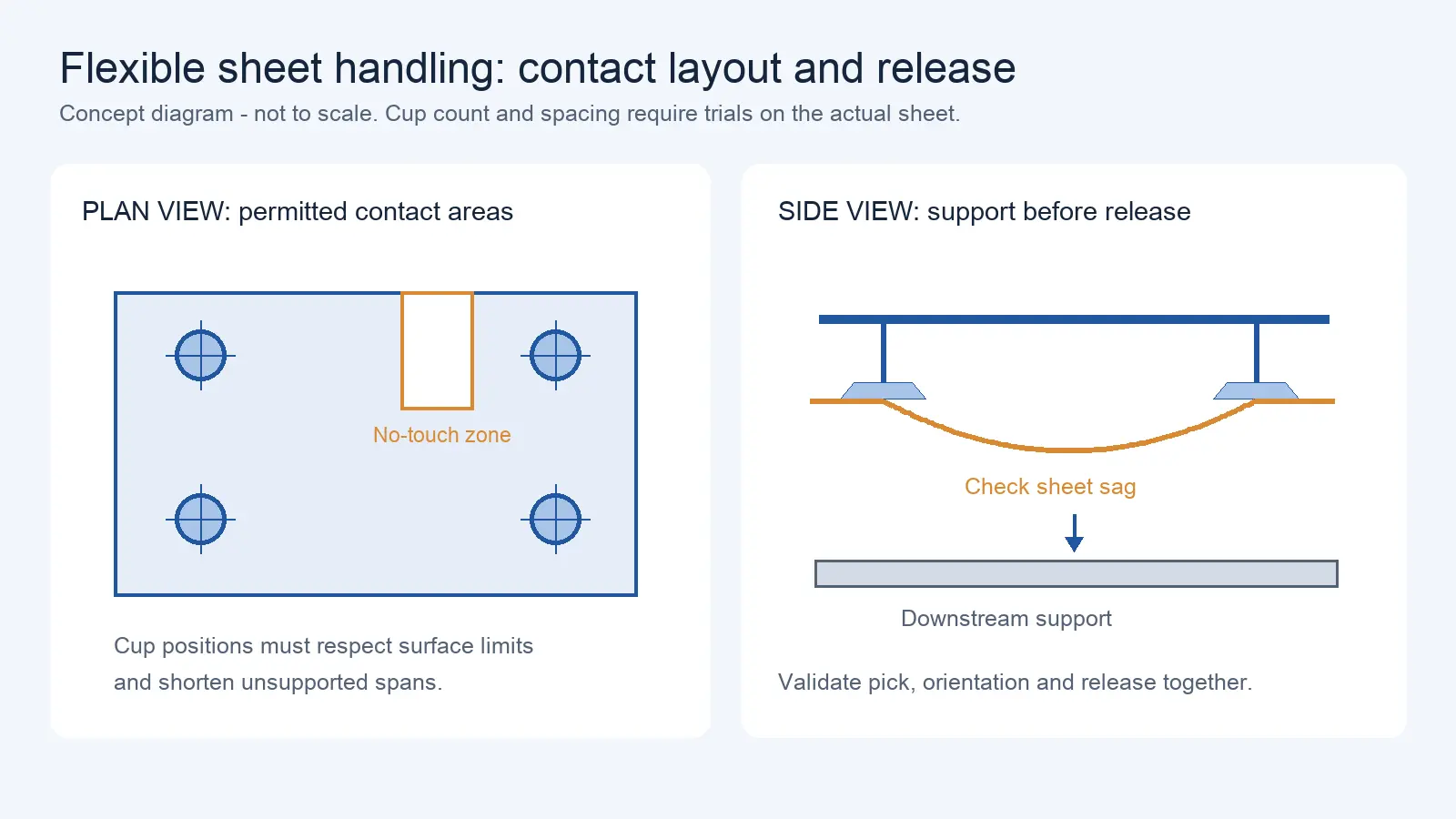
Suction Cup Layout for Flexible Sheets: Sag, Local Stress, and Controlled Release
Oct 12, 2026
A robot that performs one task needs one tool. A robot that performs multiple tasks needs a way to change tools automatically. An automatic tool changer (ATC) is a mechanical coupling system that allows the robot to pick up and release different end-of-arm tools without human intervention. The principle is straightforward: the robot approaches a parked tool, engages the coupler, locks it, verifies the lock, confirms the tool identity, and begins the new task. In practice, each of these steps can fail in ways that are not visible until production stops. This article covers what to verify when selecting and integrating an automatic tool changer, from payload capacity through failure recovery.
When Automatic Tool Change Is Actually Useful
Not every multi-task application justifies an automatic tool changer. The decision depends on:
- Change frequency: If tools are changed once per shift, manual change may be more cost-effective than an ATC system
- Tool count: Two tools may be handled with a simple parking stand. Five or more may require a carousel or multiple stands.
- Downtime cost: If each minute of changeover costs significant production, the ATC's automated cycle may pay for itself quickly
- Operator availability: If no operator is present during the shift, automatic changing may be the only option
- Process repeatability: If tool-to-tool positioning accuracy is critical, an ATC with repeatability specification may outperform manual change
The ATC is a solution for a specific problem: frequent, accurate, unattended tool changes. It is not a universal requirement for any robot that uses more than one tool. The buyer should evaluate whether the change frequency and accuracy requirements justify the cost and complexity of an ATC system before specifying one.
Start with the robot gripper selection guide to determine whether different workpieces actually require different end effectors.
Payload, Offset, Moment, and Inertia at Both Interfaces
A tool changer adds mechanical components between the robot wrist and the EOAT. The coupler (mounted on the robot) and the adapter (mounted on the tool) each add mass, length, and a moment arm. This changes the payload and inertia at the robot wrist.
The payload calculation must include:
- Tool weight: The mass of the EOAT including grippers, sensors, and process tools
- Coupler and adapter mass: The tool changer components themselves
- Payload (part or workpiece): The mass of whatever the tool is handling
- Center of gravity offset: The distance from the wrist faceplate to the CG of the combined load. The tool changer adds length, which increases the moment arm and the effective load on the wrist.
- Inertia: The rotational inertia of the combined load, which affects the robot's ability to accelerate and decelerate the tool
The robot manufacturer specifies maximum payload, maximum moment, and maximum inertia at the wrist. The tool changer manufacturer specifies maximum payload and moment for the coupler-adapter pair. The system must satisfy both limits simultaneously, at the worst-case position and during the worst-case motion. A tool that is within the robot's payload limit may exceed the tool changer's lock capacity, or vice versa.
ISO 9409-1:2004 defines the dimensions of the circular mounting plate used at the robot wrist (the mechanical interface). It specifies the bolt circle diameter, the number and size of bolts, and the pilot diameter. It does not specify coupling load capacity, locking force, or any performance characteristic of a tool changer. A tool changer that matches the ISO 9409-1 interface dimensions will physically fit the robot wrist, but its load capacity must be verified separately from the dimensional standard.
Mechanical Locking and Positive Confirmation
A tool changer must do more than physically connect the tool. It must lock the connection and provide positive confirmation that the lock is engaged. Without confirmation, the robot may begin a task with a tool that is engaged but not locked, which can result in the tool dropping during motion.
The locking mechanism typically uses a spring-loaded or pneumatically actuated mechanism that engages locking balls or pins into a receiver. The confirmation system uses sensors (typically proximity switches or pneumatic pressure switches) that detect the locked position.
Engaged is not locked
The distinction between “engaged” and “locked” is critical. Engaged means the coupler and adapter are physically mated. Locked means the locking mechanism has been actuated and confirmed. A tool can be engaged but not locked if the locking mechanism fails to actuate, if a sensor is faulty, or if debris prevents full lock engagement.
The robot program should not proceed to the task until the lock confirmation sensor indicates “locked.” If the sensor indicates “engaged but not locked” or “no signal,” the program should stop and trigger an alarm. The interlock logic should be designed so that a missing lock signal prevents any motion that could drop the tool.
The failure mode to prevent is a tool that is physically attached but not locked, being swung through a motion at full speed. The locking mechanism may hold during slow motion but release under the dynamic forces of rapid motion, dropping the tool and potentially causing damage or injury.
Utilities: Air, Vacuum, Power, Fluid, and Data
Most tool changers provide pass-through connections for utilities: pneumatic lines, electrical power, fluid lines, and data signals. These pass-throughs allow the robot to connect and disconnect utilities automatically when changing tools.
For each tool, the team must verify:
- Number of pass-through channels: Does the changer provide enough channels for all the utilities the tool requires?
- Rated capacity per channel: Is the electrical channel rated for the current and voltage the tool draws? Is the pneumatic channel rated for the pressure and flow the tool requires?
- Data signal integrity: Does the data channel support the communication protocol and data rate the tool uses? Some changers support analog or digital I/O but not high-speed fieldbus.
- Medium isolation: Are channels for different media (e.g., air and fluid) isolated to prevent cross-contamination?
- Wear and replacement: Pass-through contacts and seals wear over time. How are they inspected and replaced?
Rated connector and pass-through limits
Each pass-through channel has a rated capacity specified by the tool changer manufacturer. Exceeding that rating can cause contact failure, seal degradation, or signal integrity problems. The ratings are not interchangeable: a channel rated for 24V DC at 2A is not suitable for a 240V AC load, even if the connector physically fits.
The buyer should list every utility required by every tool, with its electrical, pneumatic, and fluid specifications, and verify that the selected tool changer can accommodate all of them simultaneously. If the changer does not have enough channels or the channels are not rated for the required loads, a different changer or additional pass-through modules are needed.
Tool Identity and Configuration Selection
When the robot picks up a different tool, the control system must know which tool is now attached. Running a program intended for a different tool can cause collisions, process errors, or damage.
Tool identification methods include:
- Mechanical coding pins: Physical pins on the adapter that are read by sensors on the coupler. Each tool has a unique pin pattern.
- RFID tags: A tag on the adapter that stores the tool ID and optionally calibration data.
- Barcode or QR code: Read by a vision sensor on the robot.
- I/O mapping: The tool's I/O configuration is read by the controller, and the pattern identifies the tool.
After the tool ID is confirmed, the robot program should automatically select the correct:
- TCP (Tool Center Point): The position of the tool tip relative to the wrist faceplate
- Payload and CG: The mass and center of gravity of the new tool plus any part
- I/O mapping: Which inputs and outputs correspond to the new tool's sensors and actuators
- Program version: The motion program appropriate for the new tool
If any of these does not match the confirmed tool ID, the program should stop and alarm. The system should not allow a tool to be used with a program written for a different tool, even if the operator believes the combination is safe.
For tool changes that alter TCP or measurement references, robot calibration management covers the evidence and recalibration triggers.
Parking Nests and Layout Dependencies
The parking station (or nest) is where tools are stored when not in use. Its design affects the reliability of the tool change sequence:
- Support: The nest must support the tool's weight and prevent it from shifting
- Positioning tolerance: The nest must locate the tool precisely enough that the robot can engage the coupler within the changer's allowable misalignment
- Contamination protection: The coupler and adapter faces should be protected from dust, coolant, and chips when parked
- Error detection: The nest should detect if a tool is present or absent, and if a tool is incorrectly parked (e.g., rotated 90 degrees)
- Maintenance access: The nest must be accessible for cleaning, inspection, and manual tool removal
- Robot approach path: The robot must be able to approach and withdraw from the nest without colliding with other equipment
Change Sequence and Failure Recovery
A complete tool change sequence includes:
- Return current tool to parking nest
- Confirm tool is seated in nest
- Release coupler lock
- Withdraw from adapter
- Move to new tool's parking nest
- Engage coupler with adapter
- Lock and confirm
- Verify tool ID
- Check utility pass-through (air pressure, electrical continuity, data communication)
- Select new TCP, payload, and program
- Proceed to task
If any step fails, the system must enter a defined recovery state. The recovery state should prevent the robot from proceeding with an incomplete or incorrect tool change.
Store tool ID and program references under controlled robot configuration management, rather than relying on an operator memory of the last tool.
Tool misidentification or interrupted swap
If the tool ID does not match the expected tool after a change, the system must stop. The program should not attempt to “use whatever tool is attached.” The operator or maintenance team must investigate why the wrong tool was picked up (e.g., tool parked in the wrong nest, sensor failure, program error).
If the change sequence is interrupted (e.g., E-stop during engagement), the system may be in an unknown state: the tool may be partially engaged, partially locked, or not connected at all. The recovery procedure must handle this state safely. The robot should not attempt to move until the tool status is confirmed. If the status cannot be confirmed automatically, manual inspection is required.
Serviceability and Wear Points
Tool changers have mechanical wear points that affect long-term reliability:
- Coupling faces: The mating surfaces between coupler and adapter wear with repeated cycles, changing the positioning repeatability
- Seals: Pneumatic and fluid seals degrade over time, causing leaks
- Electrical contacts: Spring-loaded contacts wear and may develop resistance or intermittent connections
- Locking mechanism: Balls, pins, and cams wear, potentially reducing lock reliability
- Sensors: Proximity switches and pressure switches can fail or drift
The maintenance plan should include periodic inspection of these wear points, with replacement intervals based on the number of change cycles and the operating environment. The tool changer manufacturer should provide expected cycle life for the coupler and adapter, but actual life depends on the specific application.
Representative Tool Change Acceptance Tests
Before accepting a tool changer system for production, the following tests should be performed:
- Heaviest tool change: Change the heaviest tool in the set, including engagement, lock, and utility verification
- Offset CG tool: Change a tool with the worst-case center of gravity offset to verify that the coupler handles the moment load
- High-frequency change: Perform multiple consecutive changes to verify that the system does not degrade over a representative number of cycles
- Contamination test: If the environment is dusty or wet, verify that contamination does not prevent engagement or lock confirmation
- Power-loss test: Simulate a power or air loss during a change to verify that the tool remains locked (fail-safe design) or that the recovery procedure handles the state correctly
- Wrong-tool test: Attempt to pick up the wrong tool and verify that the system detects and rejects it
A single successful empty-load tool change is not sufficient evidence that the system will perform reliably in production. The acceptance test must cover the full range of tools, loads, and failure modes.
ISO 11593:2022 defines the vocabulary for automatic end-effector exchange systems, including terms such as “couple,” “uncouple,” “lock,” and “unlock.” It provides a common language for specifying and discussing tool changer requirements. It does not specify performance requirements, load ratings, or test methods for tool changers. The standard is useful for ensuring that the buyer, supplier, and integrator use consistent terminology, but it does not replace the need for manufacturer-specific technical data and application testing.
Comparing robot configurations for several tools? Send the robot model, number of tools, individual tool weights and center-of-gravity offsets, required air/electric/data connections, and expected change frequency. AIsirRobot can help compare available tooling options and list lock-sensing or interface details requiring manufacturer confirmation.
Share on Social:


Contact Us
In This Article
Delivery Robot Accessibility: Tray Reach, Controls, and Assisted Handoffs
Oct 12, 2026
Commercial Carpet-Vacuuming Robots: Pile, Edge Transitions, and Maintenance Limits
Oct 12, 2026
Robotic TIG Filler-Wire Delivery: Feed Angle, Arc Access, and Stop-Start Quality
Oct 12, 2026
Suction Cup Layout for Flexible Sheets: Sag, Local Stress, and Controlled Release
Oct 12, 2026