

 Contact Us

 Home /
 Robot Gripper Selection Guide: Vacuum, Mechanical, Magnetic, and Soft Grippers Compared
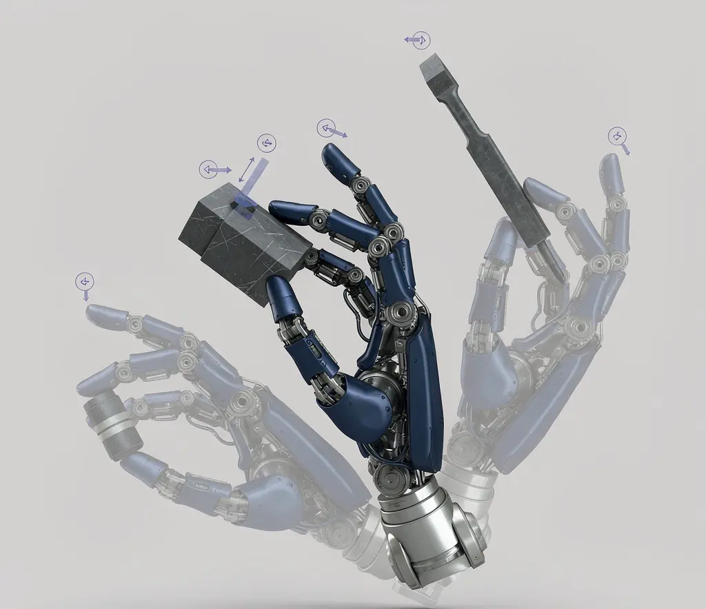
Humanoid Robot Hand Dexterity Verification: Grasp Set, Tool Use, Force Control, and Recovery
Oct 08, 2026

Industrial Exoskeleton Fit and Sizing: Anthropometry, Adjustment Time, PPE, and Shared-Device Programs
Oct 08, 2026

Robot Duty Cycle and Thermal Limits: Why Rated Payload and Speed Do Not Guarantee Continuous Operation
Oct 08, 2026

Robot IP Ratings Explained: What IP54, IP65, and IP67 Do — and Do Not — Prove
Oct 08, 2026
The gripper is the part of the robot that actually touches your product. Get it wrong, and the most precise robot arm with the best vision system will still drop parts, deform them, or fail to pick them up at all. Gripper selection starts not with the gripper catalog but with the part: its material, geometry, surface, weight, and what happens when you grip it. This guide compares vacuum, mechanical, magnetic, and soft grippers by what they do well, where they fail, and what infrastructure they need — then walks through payload calculations, tool changers, cleanliness requirements, and part presence detection so you can specify an EOAT that works on your production floor, not just in a demo.
Start With the Part, Not the Gripper Catalog
Before comparing gripper types, document the part you need to handle. Every gripper decision flows from these part characteristics:
| Part Characteristic | Why It Matters for Gripper Selection |
| Material | Determines whether vacuum, magnetic, or mechanical gripping is physically possible |
| Surface finish | Smooth, porous, rough, oily, wet — affects suction cup adhesion and friction coefficient |
| Geometry | Flat, cylindrical, irregular, thin-walled — determines contact geometry and gripper finger design |
| Weight | Determines required gripping force, vacuum cup size, or magnetic holding force |
| Center of gravity | Affects gripper orientation and wrist moment calculation |
| Allowed contact force | Can the part withstand clamping pressure, or will it deform or break? |
| Temperature | Hot or cold parts may require special gripper materials |
| Cleanliness requirements | Food-grade, cleanroom, or medical applications constrain material and design choices |
A part made of porous cardboard can make conventional vacuum gripping unreliable and may require high-flow or specialized vacuum systems. A part made of aluminum eliminates magnetic gripping — aluminum is not ferromagnetic. A part with a delicate surface limits high-force mechanical gripping — the fingers may leave marks or cause deformation.
These are not preferences. They are physical constraints.
Vacuum Grippers: Where Suction Works and Fails
Vacuum grippers use suction cups to create a pressure differential between the cup and the workpiece. The atmosphere pushes the part against the cup, holding it in place.
Where vacuum works:
- Flat or smoothly curved surfaces (glass, sheet metal, plastic sheets, cardboard boxes with smooth surfaces)
- Parts where surface contact is acceptable and does not cause damage
- Applications requiring fast pick-and-place with simple part geometry
Where vacuum fails:
- Porous materials: Cardboard, MDF, textiles, sintered metals — vacuum leaks through the material surface, preventing pressure differential. Some vacuum gripper designs address this with higher flow rates or specialized cup geometries, but the underlying physics remains a challenge.
- Rough or uneven surfaces: Gaps between the cup and surface prevent seal formation.
- Wet or oily surfaces: May reduce friction coefficient and cause slippage during acceleration.
- Heavy parts with small contact area: Holding force is proportional to cup area and vacuum pressure. Small cups on heavy parts may not generate sufficient force.
Suction cup selection factors:
- Cup material: Rubber, silicone, polyurethane — each with different friction coefficients, temperature ranges, and chemical resistance.
- Cup diameter: Determines holding force. Larger diameter = more holding force, but requires more surface area on the part.
- Vacuum pressure level: Higher vacuum = more holding force, but requires more powerful (and often louder) vacuum generation.
- Number and arrangement of cups: Multiple cups distribute load and provide redundancy if one cup loses seal.
An academic model (Mantriota, Mechanism and Machine Theory, 2007) provides a mathematical framework for vacuum gripper selection: calculating minimum static friction coefficient and vacuum level to guarantee firm grasp without detachment or slipping. The model accounts for object weight, acceleration forces, cup diameter, vacuum pressure, and friction coefficient. This is one of the few peer-reviewed theoretical frameworks for gripper selection — most selection guidance comes from manufacturer catalogs rather than academic literature.
Infrastructure requirement: Vacuum grippers require compressed air or an electric vacuum pump. If your facility does not have compressed air, you need an electric vacuum generator, which adds cost and electrical load.
Mechanical Grippers: Force, Stroke and Contact Geometry
Mechanical grippers use fingers or claws to apply gripping force. They are the most versatile gripper type — they can handle a wider range of part geometries than vacuum or magnetic grippers — but their selection requires more calculation.
Two gripping principles:
- Friction-based gripping: The gripper applies normal force, and friction between the fingers and the part prevents slipping. Force required = normal force × friction coefficient. This method depends on the friction coefficient between the finger material and the part surface — which changes with surface contamination, temperature, and wear.
- Form-closed gripping: The finger geometry matches the part geometry. A V-groove finger for cylindrical parts, a custom-contoured finger for complex shapes. The part is held by geometric constraint, not friction. This is more reliable for defined part shapes because it does not depend on friction coefficient.
Key parameters:
| Parameter | What to Specify |
| Gripping force (N) | Must exceed the force required to hold the part under maximum acceleration |
| Stroke (mm) | Must accommodate the range of part sizes if handling multiple variants |
| Contact geometry | Flat fingers, V-groove, custom contour — must match part geometry |
| Finger material | Steel, aluminum, rubber-coated, polyurethane — affects friction, part marking, and wear |
| Repeatability | How precisely the fingers return to the same position |
| Actuation type | Pneumatic or electric — determines infrastructure and control precision |
Where mechanical grippers work well:
- Rigid parts with defined geometry
- Applications requiring precise part positioning
- Parts that can withstand clamping force without deformation
Where mechanical grippers struggle:
- Delicate or fragile parts (risk of deformation or breakage)
- Parts with varying geometry (requires adjustable or custom fingers)
- High-speed applications where finger open/close cycle time is a bottleneck
Magnetic Grippers: Material Limits and Residual Magnetism
Magnetic grippers use magnetic fields to attract ferromagnetic parts. They are simple, fast, and require no compressed air — but they have a hard material limitation.
Material limitation: Magnetic grippers only work with ferromagnetic materials — steel, iron, and some stainless steel grades. They cannot grip aluminum, copper, brass, plastics, or austenitic stainless steel grades (which are non-magnetic). This is a physical constraint, not a design preference.
Two magnetic gripper technologies:
| Technology | How It Works | Power Failure Behavior | Energy Use |
| Electro-permanent magnet | Short electrical pulse switches magnetic field on/off | Can reduce unintended load drop during power loss | Very low — only pulse power needed |
| Electromagnet | Continuous electric current maintains magnetic field | Releases part immediately on power loss | Higher — continuous power required |
Electro-permanent magnets can reduce unintended load drop during power loss, which may be advantageous for applications where dropped parts pose a safety or damage risk. Whether this is “safer” depends on the application risk assessment — in some scenarios, immediate release on power loss is the desired safety behavior. They require only a brief electrical pulse to switch states, then hold without power. Electromagnets release the part the moment power is interrupted — which may be desirable for some safety scenarios but dangerous for others.
Residual magnetism: Permanent magnet grippers may leave residual magnetism on the workpiece. This is problematic for:
- Precision electronics (residual field can affect sensitive components)
- Parts requiring subsequent magnetic-sensitive processes
- Parts where residual magnetism attracts ferrous contamination
Where magnetic grippers work well:
- Steel sheets, plates, bars, and ferrous components
- Applications where five-side access to the part is needed (magnetic grippers contact only one surface)
- Heavy ferromagnetic parts where mechanical gripper force would be insufficient
Where magnetic grippers fail:
- Non-ferromagnetic materials (aluminum, copper, plastics, austenitic stainless steel)
- Parts where residual magnetism is unacceptable
- Applications requiring precise part orientation (magnetic grip does not control rotation around the field axis)
Soft Grippers: Delicate and Irregular Parts
Soft grippers use compliant materials that conform to the object’s shape. Inspired by biological designs (starfish, octopus, jellyfish), they inflate, bend, or wrap around objects to grip them.
Where soft grippers work:
- Delicate items that cannot withstand clamping force (fruit, baked goods, electronic components)
- Irregular shapes that do not match any fixed finger geometry
- Items where surface contact area needs to be maximized to distribute force
Technology maturity: Soft grippers are commercially available for specific applications — particularly food handling and delicate item manipulation. They are less mature than vacuum, mechanical, or magnetic grippers for general industrial use.
Limitations:
- Payload capacity: Typically lower than other gripper types. Commercial soft grippers handle loads in the range of 900 g to 4,140 g depending on model.
- Wear and fatigue: Soft materials degrade over time, especially with repeated cycling.
- Precision: Lower positioning precision than mechanical grippers.
- Cycle time: Inflation/deflation takes longer than pneumatic finger actuation.
- Pneumatic dependency: Most soft grippers require pneumatic actuation (inflation/deflation).
What buyers must verify:
- Payload capacity for your specific part weight
- Cycle time compatibility with your production rate
- Material durability and expected replacement frequency
- Whether replacement parts are available and at what cost
Payload, Center of Gravity and Wrist Moment
The gripper is not the only thing on the end of the robot arm. The total end-of-arm weight includes everything between the wrist flange and the part:
Total EOAT weight = gripper + adapter plate + sensors + cables + connectors
This total weight consumes robot payload capacity. A 5 kg gripper assembly on a 10 kg payload robot leaves only 5 kg for the actual workpiece. If the workpiece weighs 6 kg, the robot is overloaded — regardless of what the gripper catalog says.
EOAT Payload Worksheet
| Component | Weight (kg) |
| Gripper body | |
| Adapter plate / mounting bracket | |
| Fingers or suction cups | |
| Sensors (force/torque, proximity, vision) | |
| Cables and connectors | |
| Tool changer (if used) | |
| Total EOAT weight | |
| Robot payload capacity | |
| Remaining payload for workpiece | |
| Actual workpiece weight | |
| Payload margin (positive = OK) |
Wrist moment is the other critical calculation. Static wrist moment ≈ mass × gravitational acceleration × distance from the wrist reference point to the combined center of gravity of the EOAT assembly. This must not exceed the robot’s rated wrist torque and inertia limits. Also verify the manufacturer’s allowable wrist torque and inertia limits under dynamic motion, as dynamic loads during acceleration and deceleration can significantly exceed static values.
A gripper that is within the payload limit but extends far from the wrist (long adapter plate, extended fingers) may exceed the wrist moment limit. The robot will not refuse to run — it will simply perform worse, with reduced accuracy, increased vibration, and premature wear on wrist bearings.
Consider an integrator who selects a 3 kg gripper with a 150 mm adapter plate for a robot rated at 10 kg payload. The workpiece weighs 4 kg, so the total EOAT plus workpiece is 7 kg — well within the 10 kg limit. But the wrist moment, calculated as the total EOAT weight multiplied by the distance from the wrist center to the EOAT center of gravity, exceeds the robot’s rated wrist moment. The robot runs, but accuracy drops, cycle times increase due to vibration settling, and wrist bearing failure appears within months instead of years.
Air, Power, Sensors and Failure Detection
Grippers need infrastructure. What they need depends on the type:
| Gripper Type | Infrastructure Required |
| Vacuum | Compressed air or electric vacuum pump |
| Mechanical (pneumatic) | Compressed air |
| Mechanical (electric) | Electrical power, communication cable |
| Magnetic (electro-permanent) | Electrical power (pulse) |
| Magnetic (electromagnet) | Continuous electrical power |
| Soft | Pneumatic supply |
Part presence detection is not optional — it is a safety requirement. Dropped parts can damage equipment, injure personnel, and disrupt production. Common detection methods:
| Detection Method | How It Works | Best For |
| Vacuum pressure switch | Verifies vacuum level for suction grippers | Vacuum grippers — confirms part is held |
| Mechanical position sensor | Confirms finger position (open/closed/part present) | Mechanical grippers |
| Proximity sensor | Detects part presence without contact | Any gripper type — non-contact verification |
| Vision system | Confirms part presence and orientation | High-precision applications, multi-variant production |
What buyers must specify:
- Detection method for each gripper type used
- Failure response: What happens when the gripper loses the part? (Stop immediately? Alert operator? Attempt retry? Continue to next position?)
- Whether detection is per-gripper or system-level
Tool Changers for High-Mix Production
If your robot handles multiple part types that require different grippers, you need a tool changer. ISO 9409-1 standardizes certain mechanical interface dimensions for industrial robot end-effectors. A gripper or tool changer with an ISO 9409-1-compatible pattern may simplify mounting on robots with the same interface, but does not by itself guarantee dynamic compatibility, payload suitability, or inertia matching — verify with the specific robot manufacturer’s load and moment specifications.
Two tool changer types:
| Type | How It Works | When to Use |
| Manual tool changer | Operator physically removes and installs tools | Low changeover frequency (once per shift or less) |
| Automatic tool changer | Pneumatic or electric mechanism switches tools without operator | High changeover frequency (multiple times per hour) |
For high-mix production, specify:
- Tool changer compatibility (ISO 9409-1 pattern, plates form A, or custom)
- Automatic vs manual change (based on changeover frequency)
- Tool storage solution (tool tree or rack for storing tools when not in use)
- Changeover time requirement (how fast must the switch happen?)
- Whether the tool changer includes pneumatic and electrical pass-through (for grippers that need air and power)
Automatic tool changers add weight to the EOAT assembly — the amount varies by payload class; verify the specific weight with the manufacturer and include it in your payload calculation.
Cleanroom and Food-Grade Requirements
Some applications constrain gripper material selection and cleanability:
Cleanroom (ISO 14644-1:2015)
ISO 14644-1 classifies cleanrooms from Class 1 (strictest) to Class 9 (least strict) based on maximum allowable particle concentration per cubic meter. Robots and grippers used in cleanrooms must meet the particle emission limits for the target class.
What to specify:
- Required ISO 14644 class
- Particle emission limits for the gripper
- Approved cleaning methods (wipe, wash, IPA)
- Material requirements (low outgassing, non-shedding)
Food-Grade (FDA 21 CFR 177)
FDA 21 CFR 177 specifies requirements for food-grade material safety for materials that contact food products. Grippers used in food handling must use compliant materials.
What to specify:
- FDA food-grade material compliance
- Hygienic design (no crevices where food particles can accumulate)
- Cleanability (wash-down compatible, chemical resistance)
- Material certification documentation
Grippers designed for food applications typically use hygienic construction — smooth surfaces, no hidden crevices, materials that withstand wash-down cleaning. These are not the same as standard industrial grippers with food-grade material substitution.
A Robot Gripper RFQ Checklist
Part-to-Gripper Requirement Sheet
| Part Parameter | Your Value |
| Part material | |
| Surface finish (smooth/porous/rough/oily/wet) | |
| Part geometry (flat/cylindrical/irregular) | |
| Part weight | |
| Part center of gravity | |
| Allowed contact force | |
| Temperature range | |
| Cleanliness requirement (none/food-grade/cleanroom) | |
| Number of part variants | |
| Required cycle time (picks per minute) | |
| Part presentation (tray/conveyor/bin/random) |
Gripper Decision Matrix
| Requirement | Vacuum | Mechanical | Magnetic | Soft |
| Smooth, non-porous surface | ✅ | ✅ | ✅ (if ferromagnetic) | ✅ |
| Porous surface | ❌ | ✅ | ✅ (if ferromagnetic) | ✅ |
| Ferromagnetic material | ✅ | ✅ | ✅ | ✅ |
| Non-ferromagnetic metal | ✅ | ✅ | ❌ | ✅ |
| Delicate/fragile part | ✅ | ⚠️ (low force) | ✅ | ✅ |
| Heavy part | ⚠️ (large cups) | ✅ | ✅ | ❌ |
| Irregular geometry | ⚠️ | ⚠️ (custom fingers) | ❌ | ✅ |
| High-speed cycle | ✅ | ✅ | ✅ | ⚠️ (slower) |
| No compressed air available | ⚠️ (electric pump) | ✅ (electric) | ✅ | ❌ |
| Food-grade | ⚠️ (material) | ⚠️ (design) | ⚠️ (material) | ✅ |
| Cleanroom | ⚠️ (low particle) | ⚠️ (low particle) | ✅ | ⚠️ |
Request a Quote or Technical Evaluation
Tell us what you need the robot to do. Even if some technical details are not yet confirmed, our team can help evaluate suitable options.
Please share, if available: application, key requirements, site and integration conditions, quantity, destination, and target timeline.
Send Your RequirementsRFQ Items to Specify
- Part material, geometry, surface, weight, and CG
- Required cycle time and picks per minute
- Number of part variants and required changeover method
- Gripper type(s) required (vacuum/mechanical/magnetic/soft — or multiple with tool changer)
- Infrastructure available (compressed air, electrical power)
- Cleanliness requirements (ISO 14644 class, FDA food-grade, or none)
- Part presence detection method and failure response
- Tool changer requirement (manual/automatic, ISO 9409-1 compatibility)
- Total EOAT weight calculation (gripper + adapter + sensors + cables + tool changer)
- Wrist moment verification
- Payload margin after EOAT weight
- Finger or cup material specification
- Spare parts package (wear items: cups, fingers, seals)
- Replacement frequency estimate for wear components
Key Takeaways
- Start with the part, not the gripper catalog. Material, surface, geometry, and weight determine which gripper types are physically possible. Porous surfaces can make conventional vacuum gripping unreliable. A non-ferromagnetic part eliminates magnetic. A fragile part limits mechanical force.
- Each gripper type has distinct failure modes. Vacuum fails on porous surfaces. Mechanical risks part deformation. Magnetic requires ferromagnetic materials. Soft has limited payload and slower cycle times.
- Total EOAT weight consumes robot payload. The gripper, adapter, sensors, cables, and tool changer all count. Calculate the total, verify the wrist moment, and confirm there is margin left for the workpiece.
- Tool changers (ISO 9409-1) are essential for high-mix production. Automatic vs manual depends on changeover frequency. The tool changer weight must be included in payload calculations.
- Cleanroom (ISO 14644) and food-grade (FDA 21 CFR 177) requirements constrain material and design. Standard industrial grippers with material substitution are not the same as purpose-built hygienic or cleanroom grippers.
- Part presence detection is a safety requirement. Specify the detection method and the failure response — what happens when the gripper drops the part.
Share on Social:


Contact Us
In This Article
Humanoid Robot Hand Dexterity Verification: Grasp Set, Tool Use, Force Control, and Recovery
Oct 08, 2026
Industrial Exoskeleton Fit and Sizing: Anthropometry, Adjustment Time, PPE, and Shared-Device Programs
Oct 08, 2026
Robot Duty Cycle and Thermal Limits: Why Rated Payload and Speed Do Not Guarantee Continuous Operation
Oct 08, 2026
Robot IP Ratings Explained: What IP54, IP65, and IP67 Do — and Do Not — Prove
Oct 08, 2026