

 Contact Us

 Home /
 Robot Force/Torque Sensor Selection: Range, Resolution, Overload, Drift, and Integration
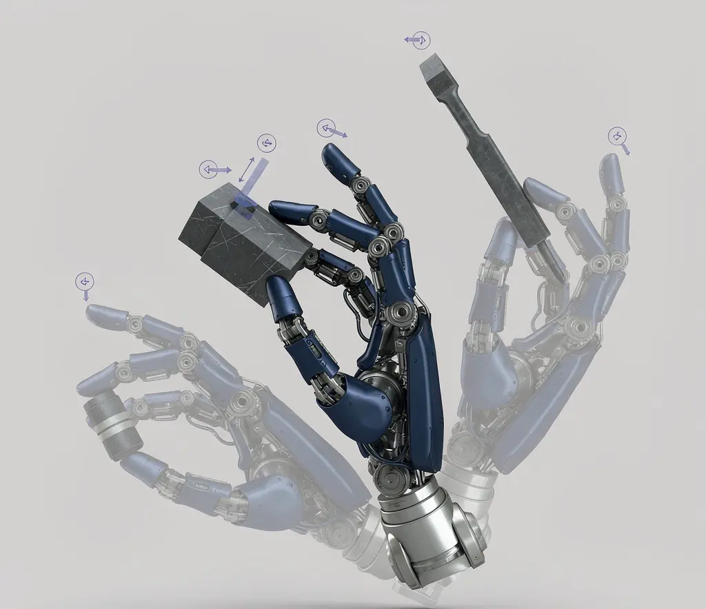
Humanoid Robot Hand Dexterity Verification: Grasp Set, Tool Use, Force Control, and Recovery
Oct 08, 2026

Industrial Exoskeleton Fit and Sizing: Anthropometry, Adjustment Time, PPE, and Shared-Device Programs
Oct 08, 2026

Robot Duty Cycle and Thermal Limits: Why Rated Payload and Speed Do Not Guarantee Continuous Operation
Oct 08, 2026

Robot IP Ratings Explained: What IP54, IP65, and IP67 Do — and Do Not — Prove
Oct 08, 2026
A robot is equipped with a six-axis force/torque (F/T) sensor to perform an assembly task that requires controlled contact force. The sensor's datasheet specifies a range of 200 N and a resolution of 0.01 N. The robot consistently fails to achieve the required assembly quality. The investigation reveals that the actual contact forces during the task are in the range of 2 to 5 N, well below the sensor's optimal measurement range. The sensor's noise floor at that level is 0.5 N, meaning the signal-to-noise ratio is too low for reliable force control. The sensor is not defective. It is the wrong sensor for the task. This article explains how to select a force/torque sensor that matches the application, avoiding the common errors of oversizing for range and confusing resolution with accuracy.
Do You Need External F/T Sensing?
Before selecting a sensor, determine whether external force/torque sensing is needed at all. There are three approaches to measuring force in a robot system:
- Joint torque estimation: The robot controller estimates force based on motor current and the robot's dynamic model. This requires no external sensor but has lower accuracy, is affected by friction and model errors, and may not detect forces at the tool tip that do not generate significant joint torque.
- Wrist-mounted F/T sensor: A six-axis sensor between the robot wrist and the EOAT measures forces and torques in all directions at the wrist. This provides direct measurement of contact forces but adds mass, length, and a cable to the wrist.
- Tool-mounted force transducer: A single-axis or limited-axis sensor mounted at the contact point (e.g., a load cell in a press head). This provides the most direct measurement at the point of interest but only in the measured directions.
The choice depends on the task. If the task requires multi-axis force control (e.g., surface following with variable normal force), a wrist-mounted six-axis sensor is appropriate. If the task requires only a single-axis force measurement (e.g., pressing to a defined force), a tool-mounted transducer may be simpler and more accurate. If the task only requires detecting contact or collision, joint torque estimation may be sufficient.
Select Measurement Range With Overload Margin
The sensor's measurement range must cover the expected process forces, but not so much that the forces of interest are a small fraction of the range. A sensor with a 500 N range measuring a 5 N process force is using 1% of its capacity, where noise and nonlinearity may be significant relative to the signal.
The range selection should consider:
- Normal process force: The expected force during successful operation
- Peak process force: Transient forces during engagement, impact, or disturbance
- Overload conditions: Forces that may occur during collisions, jams, or operator errors. The sensor must survive these without damage.
- Different axes: A six-axis sensor may have different ranges for force (Fx, Fy, Fz) and torque (Tx, Ty, Tz). The ranges should match the application's force distribution.
The overload specification defines the maximum force the sensor can withstand without permanent damage or calibration shift. The overload margin is the ratio of overload capacity to measurement range. A sensor with a 200 N range and 500% overload can survive 1000 N without damage. The overload margin must be sufficient for the worst-case non-process forces the sensor will experience.
Resolution, Noise, Accuracy, and Repeatability
These terms are often confused in sensor selection, leading to mismatched expectations.
- Resolution: The smallest change the sensor can detect, typically expressed in bits or in force units. A 16-bit ADC over a 200 N range has a theoretical resolution of 200/65536 = 0.003 N. This does not mean the sensor can measure 0.003 N forces reliably.
- Noise: The random fluctuation in the sensor output when no force is applied. Noise sets the practical detection limit. A sensor with 0.003 N resolution and 0.5 N noise cannot reliably detect forces below 0.5 N.
- Accuracy: The difference between the sensor's reported value and the true force. Accuracy includes nonlinearity, hysteresis, and repeatability. It is typically expressed as a percentage of full scale.
- Repeatability: The variation in the sensor's output for the same applied force, over multiple measurements. Repeatability is usually better than absolute accuracy but is still affected by noise and drift.
Robot repeatability versus accuracy refers to robot positioning specifications; F/T sensor resolution and uncertainty must be evaluated separately.
Static resolution vs application measurement uncertainty
A sensor datasheet may advertise a resolution of 0.01 N. This is the theoretical digital resolution, not the measurement uncertainty in the application. The actual uncertainty depends on noise, crosstalk, temperature drift, and the mounting conditions. A buyer who selects a sensor based on the advertised resolution without considering noise and drift may find that the sensor cannot reliably measure the forces their application requires.
The correct approach is to define the application's required force measurement uncertainty (the range within which the force must be known to achieve the process result) and then verify that the sensor's noise, accuracy, and drift specifications, under the application's conditions, can meet that requirement.
Overload, Mechanical Stops, and Replacement Risk
In industrial applications, sensors are subjected to forces that exceed their rated range. Collisions, jams, and operator errors can generate forces many times the process force. The sensor must survive these events or be inexpensive enough to be treated as a consumable.
Key considerations:
- Mechanical stops: Some sensors incorporate mechanical stops that limit deflection and protect the sensing element from overload. These stops have a defined overload capacity beyond which the sensor is damaged.
- Replacement procedure: If the sensor is damaged, how long does it take to replace? Is a spare kept on-site? Does replacement require recalibration?
- Calibration shift after overload: Even if the sensor survives an overload, its calibration may shift. The maintenance plan should include recalibration after any significant overload event.
Crosstalk, Drift, Temperature, and Zeroing
Six-axis F/T sensors measure force and torque in multiple axes simultaneously. Crosstalk is the unwanted signal on one axis caused by a force applied to a different axis. All multi-axis sensors have some crosstalk, specified as a percentage of the applied force. Crosstalk can cause apparent forces in axes where no force is applied, leading to incorrect control responses.
Drift is the gradual change in the sensor's zero output over time, even when no force is applied. Drift is caused by temperature changes, amplifier aging, and mechanical settling. If the zero is not periodically re-established, the drift accumulates and the sensor reports a non-zero force when no force is present.
Temperature effects include:
- Zero shift with temperature: The zero output changes as the sensor warms up or as the ambient temperature changes
- Sensitivity change with temperature: The sensor's response to a given force changes with temperature
- Self-heating: The sensor's electronics generate heat, which can affect the sensing elements
Zeroing (or “taring”) is the process of re-establishing the zero output by subtracting the current reading. Zeroing should be performed:
- At the start of each production run
- After any significant temperature change (e.g., after the robot has been idle overnight)
- After any overload event
- At a defined position where no external force is applied (the “zero position”)
Sensor zeroing and recalibration records should be handled under a consistent robot calibration management process.
Sampling, Filtering, and Control Latency
The sensor's sampling rate is the frequency at which it produces new measurements. A high sampling rate is necessary for capturing transient forces, but it does not directly translate to high control bandwidth. The control bandwidth depends on the entire signal path:
- Sensor sampling rate: How often the sensor produces a new measurement
- Filter: The sensor or controller may apply a low-pass filter to reduce noise. The filter's cutoff frequency limits the bandwidth.
- Communication: The sensor data must be transmitted to the controller. The communication protocol (analog, EtherCAT, PROFINET) has a latency and update rate.
- Controller cycle: The robot controller processes the force data and updates the motion command at its control cycle rate (typically 1-4 kHz for industrial robots).
- Mechanical response: The robot's mechanical response to a force command depends on its inertia, stiffness, and the control gains.
Sensor rate vs full robot loop
A sensor with a 7 kHz sampling rate does not give the robot 7 kHz force control. If the controller cycle is 1 kHz and the communication update is 2 kHz, the effective bandwidth is limited by the slowest element in the chain. The buyer should verify the entire signal path, not just the sensor's sampling rate, when evaluating whether the system can achieve the required force control performance.
Mounting Stack, CG, and Cable Routing
Adding an F/T sensor to the robot wrist changes the EOAT load case. The sensor adds mass, length (which increases the moment arm), and a cable. The mounting stack now includes:
- Robot wrist faceplate
- Tool changer (if present)
- F/T sensor
- EOAT mounting plate
- EOAT
Each component adds length and mass, and the cumulative effect must be within the robot's payload and moment limits. The sensor's mass and dimensions are specified in its datasheet and must be included in the payload calculation.
Sensor changes the EOAT load case
The sensor is not a zero-weight accessory. Depending on the size and measurement range, a six-axis F/T sensor may weigh from tens of grams for miniature units to over a kilogram for larger industrial models, and may add 15 to 50 mm or more of length to the mounting stack. This additional mass and moment arm must be factored into the robot's payload budget. If the robot was already near its payload limit, adding the sensor may require a larger robot or a lighter EOAT. The actual mass and dimensions must be taken from the specific sensor model's datasheet.
The sensor cable is also a dress pack consideration. The sensor requires a cable that carries power, signal, and calibration data from the sensor to the controller or amplifier. This cable must be routed through the robot's dress pack and must accommodate the full motion envelope without exceeding its bend radius or creating snag risks.
The robot gripper selection guide provides additional context on EOAT mass, wrist loads and tooling interfaces.
Task-Driven Sensor Examples
Different tasks have different sensor requirements:
- Assembly (press-fit, insertion): Requires measurement of small forces with high resolution and low noise. Overload protection is important because jams can generate large forces. The control bandwidth must be high enough to detect and respond to jams before damage occurs.
- Surface finishing (sanding, polishing): Requires measurement of normal contact forces with moderate resolution. The sensor must withstand vibration, dust, and temperature variation. Crosstalk between force axes matters because the contact direction may vary with surface curvature.
- Weight checking or contact detection: Requires only a binary or coarse measurement (is there contact or not, or is the weight above a threshold). A simple, robust sensor may be more appropriate than a high-precision six-axis unit.
These examples illustrate that the sensor selection should be driven by the task's force range, direction, accuracy, and environmental requirements, not by the sensor with the most impressive specifications. The specific force ranges, resolution targets, and bandwidth requirements must be derived from the buyer's application engineering, not from generic sensor catalog values.
Technical Comparison and Acceptance Checklist
When comparing F/T sensors, the buyer should request:
- Calibrated datasheet: Not a marketing summary, but the actual calibration certificate with nonlinearity, hysteresis, crosstalk, and noise values
- Temperature specifications: Zero shift and sensitivity change per degree
- Overload specification: Maximum force without damage and calibration shift after overload
- Sampling and filtering: Internal sampling rate, filter characteristics, and communication protocol options
- Integration documentation: How the sensor connects to the robot controller, what firmware or drivers are required, and what control modes are supported
- Maintenance documentation: Zeroing procedure, recalibration interval, and replacement procedure
- Representative trial: If possible, a trial with the actual task and parts to verify that the sensor achieves the required measurement performance under application conditions
Need force feedback for insertion, finishing or another contact task? Share the task, expected force directions and range, EOAT, robot controller and required data interface. AIsirRobot can help organize candidate configuration questions and seek supplier information on sensor range, interfaces and documentation. Application measurement performance must be validated by the responsible engineering team.
Share on Social:


Contact Us
In This Article
Humanoid Robot Hand Dexterity Verification: Grasp Set, Tool Use, Force Control, and Recovery
Oct 08, 2026
Industrial Exoskeleton Fit and Sizing: Anthropometry, Adjustment Time, PPE, and Shared-Device Programs
Oct 08, 2026
Robot Duty Cycle and Thermal Limits: Why Rated Payload and Speed Do Not Guarantee Continuous Operation
Oct 08, 2026
Robot IP Ratings Explained: What IP54, IP65, and IP67 Do — and Do Not — Prove
Oct 08, 2026