

 Contact Us

 Home /
 Lift-Top vs. Roller-Top AMR: Match the Load Transfer Interface Before Choosing the Robot
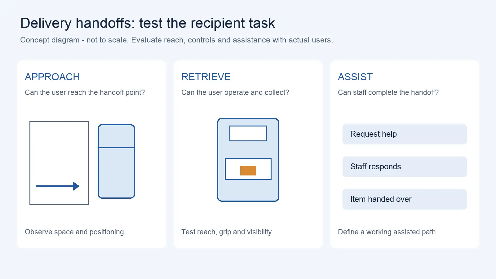
Delivery Robot Accessibility: Tray Reach, Controls, and Assisted Handoffs
Oct 12, 2026
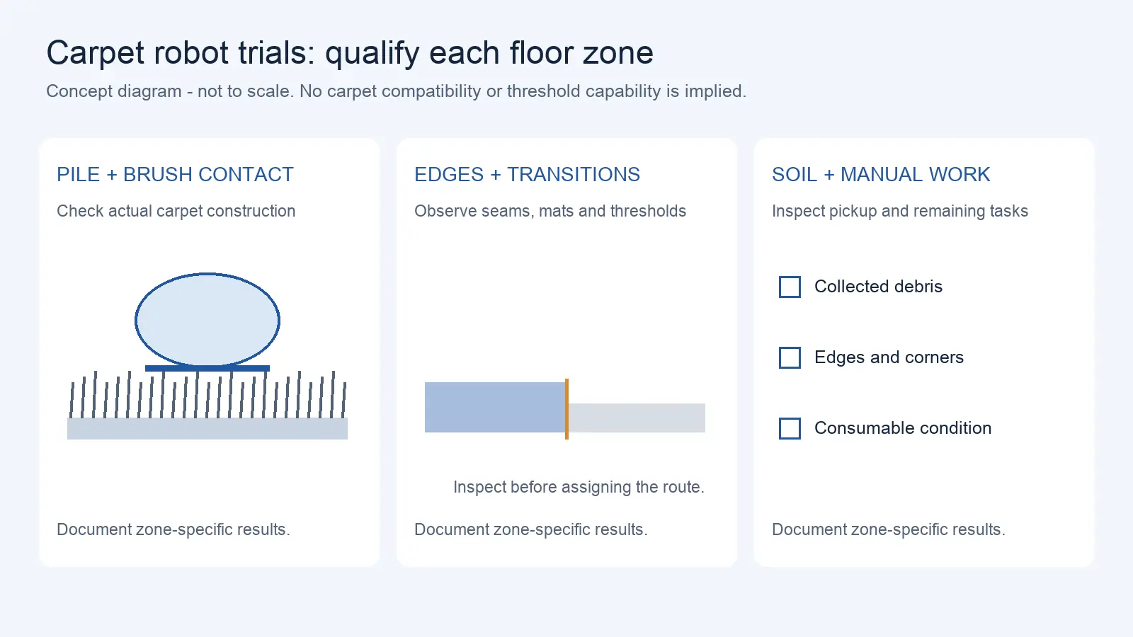
Commercial Carpet-Vacuuming Robots: Pile, Edge Transitions, and Maintenance Limits
Oct 12, 2026
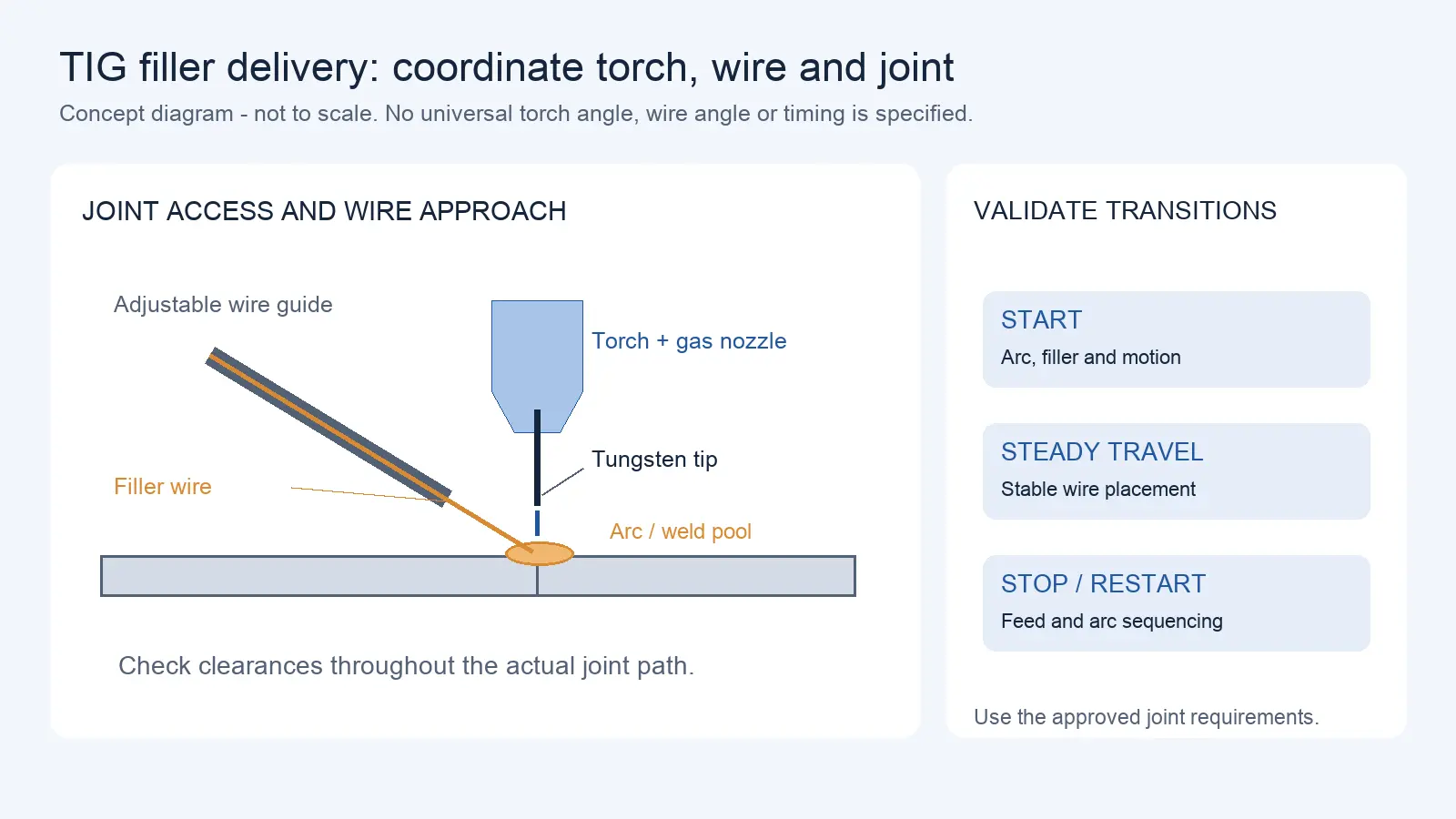
Robotic TIG Filler-Wire Delivery: Feed Angle, Arc Access, and Stop-Start Quality
Oct 12, 2026
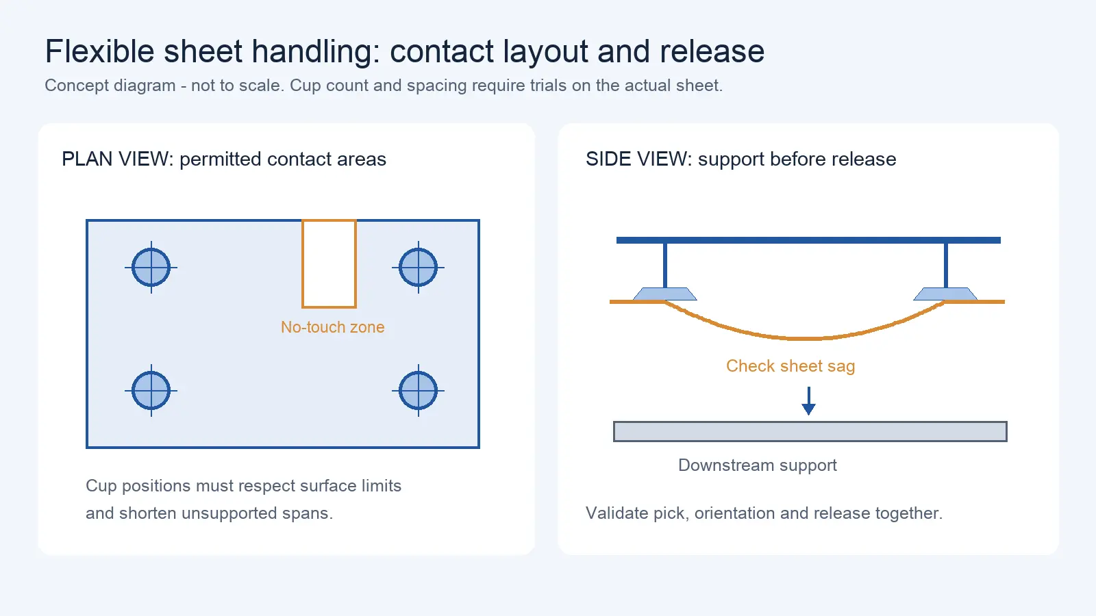
Suction Cup Layout for Flexible Sheets: Sag, Local Stress, and Controlled Release
Oct 12, 2026
AMR selection usually starts with navigation method and payload. But what actually determines whether the robot can complete the workflow is how material gets off the robot — or onto it — at each handoff point. That is the load transfer interface.
Lift-top and roller-top are the two most common transfer architectures, and they work on completely different principles. Choose the wrong one, and no amount of navigation accuracy or payload capacity will make the material flow work.
A common failure scenario: a buyer selects a lift-top AMR to interface with an existing roller conveyor line. A lift-top AMR can only raise and lower a stationary shelf or cart — it has no powered transfer surface to exchange material with a conveyor. The result is someone manually moving goods between the robot and the conveyor. Automation becomes semi-automation.
The first step in selection is defining the transfer interface: where does material come from, where does it go, what equipment is on the other end, and is the transfer passive or active?
How Lift-Top AMR Picks Up Shelves, Stands, and Carriers
The lift-top AMR works like this: the robot navigates underneath a shelf or cart → the lift mechanism raises → the shelf lifts off the ground → the robot transports it to the target position → lowers → the shelf settles on the ground → the robot drives away.
Transfer characteristics:
- The transfer is passive — the robot does not touch the material itself. It lifts the entire carrier (shelf, cart, stand).
- The carrier needs bottom clearance (leg height tall enough for the robot to drive under).
- No powered interface is needed on the fixed equipment side — a flat floor with positioning markers is enough.
- Multiple transfer points can use the same carrier standard — flexible.
Best for:
- Shelf, cart, and stand transport (goods-to-person, line-side delivery, empty carrier return)
- Transfer points where the other end has no powered conveyor
- Flexible drop-off locations (any flat floor works)
Limitations:
- Carriers must have bottom clearance matching the lift stroke
- Carrier weight + material weight + module self-weight all count against payload budget
- The lift mechanism itself has weight, reducing effective payload
- Cannot do powered transfer with conveyors
How Roller-Top AMR Exchanges Loads with Fixed Equipment
The roller-top AMR works differently: the robot navigates to the docking position → alignment sensors confirm position → rollers or belt start → material moves from the AMR to the fixed conveyor (or reverse) → sensors confirm material is in place → transfer complete.
Transfer characteristics:
- The transfer is active — the robot drives material movement via rollers or belt.
- The fixed equipment side needs a matching interface (conveyor, workstation table with rollers, etc.).
- Transfer surface height and position must match.
- Transfer direction can be one-way or two-way.
Best for:
- Interfacing with existing conveyor lines
- End-of-line automatic material pickup
- Material relay between multiple AMRs
- Continuous flow rather than whole-shelf transport
Limitations:
- The fixed equipment side needs a matching interface — but “matching” does not always mean powered. Depending on the design, the fixed end may use passive rollers, gravity rollers, or powered rollers on one side only. What matters is that material can move across the interface without stalling.
- Height and position alignment requirements depend on the transfer surface design and guide mechanism.
- Docking accuracy affects transfer success rate — but how much depends on the mechanical guides, transfer surface length, and material geometry.
Docking Position, Height, and Direction Tolerances
Both architectures require defined tolerances, but the demands are different.
| Docking parameter | Lift-top | Roller-top | Why it matters |
| Position accuracy (XY) | Medium — shelves have positioning tolerance | Depends on guide design — mechanical lead-in can compensate | Misalignment causes material jamming |
| Height matching | Low — lift mechanism compensates | High — transfer surface height must match | Height difference causes material tilt or jam |
| Direction/angle | Medium — shelves have guide angles | Depends on roller length and guide mechanism | Angular deviation causes material to slide sideways |
| Transfer surface width | N/A | Must match | Width mismatch causes material to get stuck mid-transfer |
| Sensor confirmation | Load presence detection | Material arrival + transfer complete detection | Confirms successful transfer |
For roller-top, confirm the allowable height difference, position tolerance, and angular tolerance between the AMR transfer surface and the fixed equipment. During FAT, run actual docking tests with full load — not empty docking, but loaded material transfer.
Load Stability, Transfer Direction, and Sensor Interlocks
Load stability:
- Lift-top: The load must stay stable during lifting — CG offset, lift vibration, and inertial forces during travel can all cause load shift.
- Roller-top: Material moves across rollers during transfer — if the material bottom is uneven or roller gaps are large, material can jam or tilt.
Transfer direction:
- Lift-top: Usually no directional transfer — the robot arrives, lowers, and leaves.
- Roller-top: One-way rollers can only transfer in one direction; bidirectional rollers can receive and dispatch.
Sensor interlocks:
- Before transfer: AMR confirms it is in position; fixed equipment confirms it is ready.
- During transfer: Material movement detection, jam detection.
- After transfer: Material-in-position confirmation; AMR clears to depart.
- Exception states: What happens when material jams mid-transfer, sensors disagree on whether material has arrived, or the downstream station signals “not ready”? Define the recovery sequence — who stops the transfer, who clears the jam, how the system re-syncs.
Confirm the sensor interlock logic — who initiates transfer (AMR or fixed equipment), how arrival is confirmed, how timeout is handled, and who is responsible for recovery during exceptions.
When Manual Assistance Is Still Part of the Workflow
Even with the right transfer architecture, manual assistance remains unavoidable in some scenarios:
| Scenario | Reason for manual help | Resolution direction |
| Non-standard carriers | Bottom clearance insufficient or size mismatch | Standardize carriers or customize lift mechanism |
| Temporary transfer points | No fixed equipment interface | Add fixed docking stations |
| Exception recovery | Material stuck mid-transfer after failed handoff | Manual intervention SOP |
| Mixed production lines | Some material standardized, some non-standard | Route separation |
| Startup/shutdown | First-piece confirmation and last-piece handling | Manual verification |
Track how often manual intervention is needed per shift. The acceptable frequency depends on your project SLA — some operations tolerate occasional manual help; others require near-zero intervention. If manual assistance is frequent, the transfer architecture or interface design may need rethinking.
Transfer Decision Matrix: By Pallet, Shelf, Conveyor, and Machine Interface
Material Transfer Decision Matrix
| Transfer target | Carrier type | Recommended architecture | Key confirmation | Manual assistance need |
| Floor/stand | Standard shelf | Lift-top | Shelf leg height, lift stroke | Low |
| Conveyor line | Pallet/tote | Roller-top | Height match, position tolerance | Low (if docking is well-designed) |
| Workstation | Tote/pallet | Roller-top or lift-top | Depends on whether station has power | Medium |
| Manual pickup position | Pallet/tote | Fixed platform or lift-top | Height suitable for manual pickup | High (manual pickup) |
| Multi-AMR relay | Pallet/tote | Roller-top | Bidirectional transfer, position tolerance | Low |
| Non-standard carrier | Irregular | Custom fixture | Load geometry, constraint solution | Case by case |
Transfer Interface Measurement Checklist
| Measurement item | Lift-top needs | Roller-top needs | Measurement method |
| Carrier bottom clearance (mm) | ✅ | — | Measure carrier leg height |
| Carrier max dimensions (mm) | ✅ | ✅ | Physical measurement |
| Carrier + material total weight (kg) | ✅ | ✅ | Weighing |
| Fixed equipment transfer height (mm) | — | ✅ | Measure conveyor/workstation surface height |
| Transfer surface width (mm) | — | ✅ | Measure fixed equipment transfer surface width |
| Position tolerance (mm) | — | ✅ | Evaluate AMR positioning accuracy vs. docking tolerance |
| Angular tolerance (°) | — | ✅ | Evaluate AMR angular deviation vs. docking tolerance |
| Fixed equipment powered transfer? | — | ✅ | Confirm conveyor direction and speed |
| Transfer direction (one-way/bidirectional) | — | ✅ | Confirm whether receive + dispatch needed |
| Sensor interface | Load presence | Arrival + transfer complete | Confirm sensor type and interlock |
Need Help Matching the Handoff Interface?
A lift-top or roller-top decision should start from the physical handoff. We can help review whether the robot, carrier, conveyor, and docking interface match as one system.
Please share, if available: carrier type, fixed equipment type, transfer height, transfer direction, load size and weight, docking tolerance, and sensor or interlock requirements.
Send Handoff DetailsInterface Selection Inputs
- Define the transfer interface before choosing an architecture — where material comes from, where it goes, what equipment is on the other end.
- Lift-top is passive transfer — it lifts the entire carrier — best for shelf/cart transport, not for conveyor docking.
- Roller-top is active transfer — it drives material movement — best for conveyor docking, but the fixed end needs a matching interface (passive rollers, gravity, or powered).
- Docking precision depends on guide design — mechanical lead-in and transfer surface length can compensate for positioning deviation.
- Clarify sensor interlock logic and exception states — who initiates transfer, how arrival is confirmed, what happens on jam, sensor disagreement, or downstream not ready.
- Track manual intervention frequency — define acceptable limits in your project SLA.
- Run full-load material docking tests during FAT — empty docking cannot replace loaded verification.
Share on Social:


Contact Us
Delivery Robot Accessibility: Tray Reach, Controls, and Assisted Handoffs
Oct 12, 2026
Commercial Carpet-Vacuuming Robots: Pile, Edge Transitions, and Maintenance Limits
Oct 12, 2026
Robotic TIG Filler-Wire Delivery: Feed Angle, Arc Access, and Stop-Start Quality
Oct 12, 2026
Suction Cup Layout for Flexible Sheets: Sag, Local Stress, and Controlled Release
Oct 12, 2026