

 Contact Us

 Home /
 Six vs Seven Degrees of Freedom: When Robot Arm Redundancy Helps with Access

Six vs Seven Degrees of Freedom: When Robot Arm Redundancy Helps with Access
Oct 13, 2026
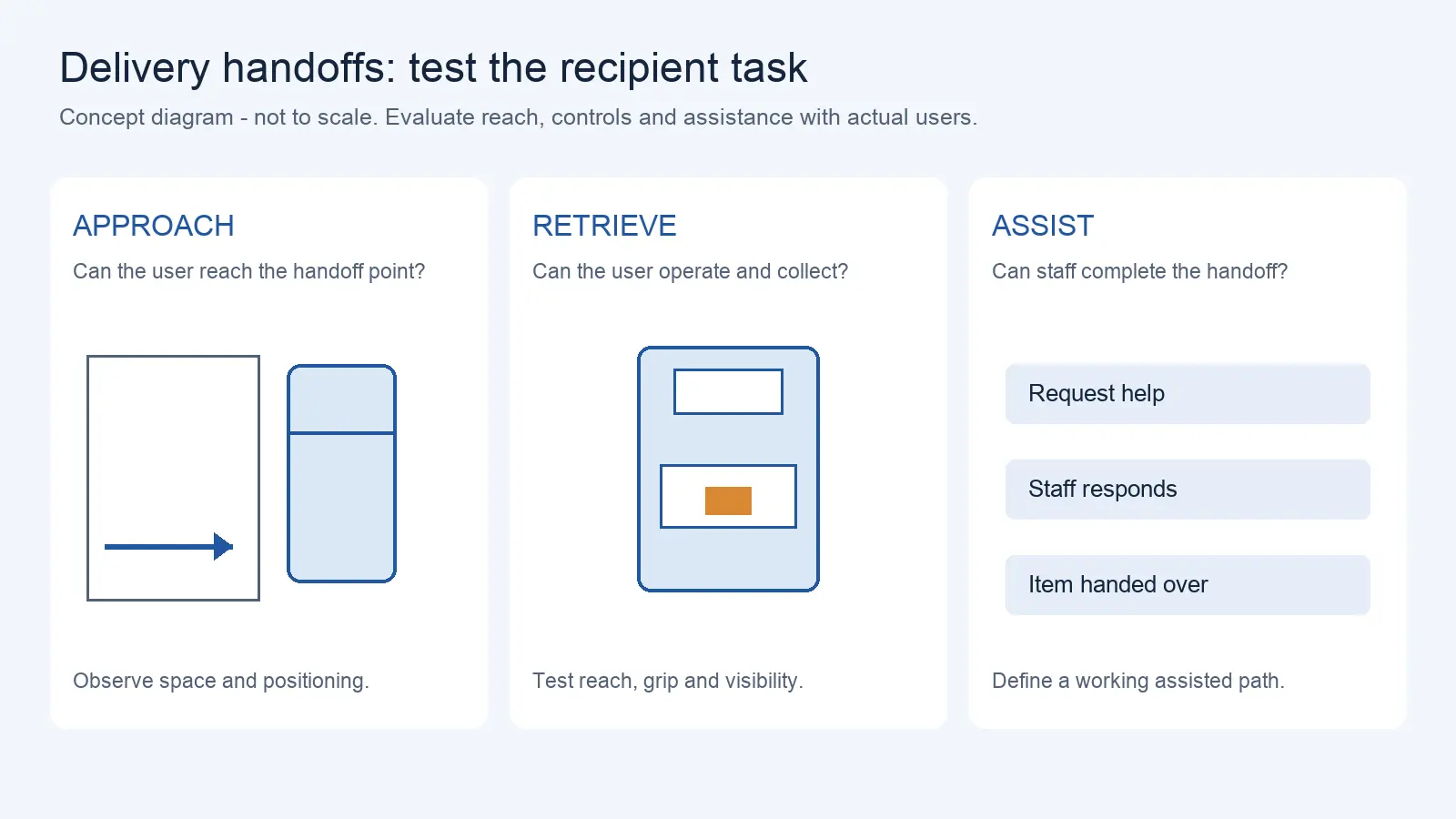
Delivery Robot Accessibility: Tray Reach, Controls, and Assisted Handoffs
Oct 12, 2026
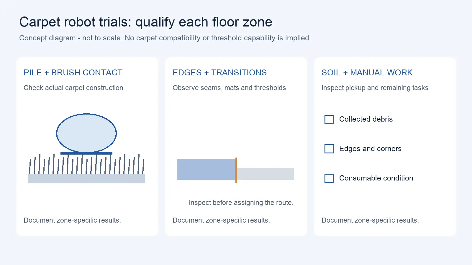
Commercial Carpet-Vacuuming Robots: Pile, Edge Transitions, and Maintenance Limits
Oct 12, 2026
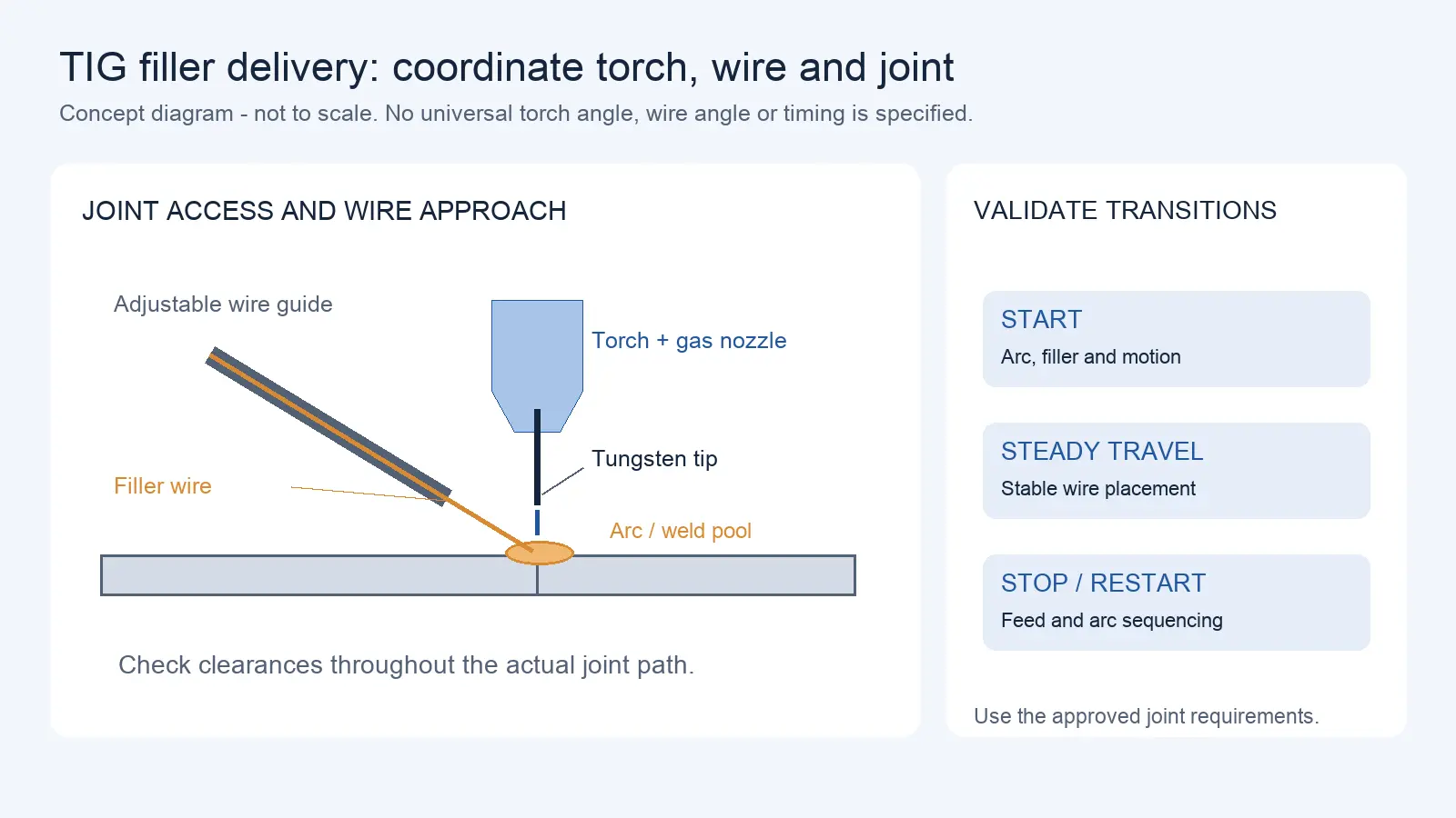
Robotic TIG Filler-Wire Delivery: Feed Angle, Arc Access, and Stop-Start Quality
Oct 12, 2026
The question of six versus seven degrees of freedom usually arrives with a specific frustration: the robot can reach the point, but it cannot get there from a workable posture. The wrist is fine, but the elbow is in the way, or the arm cannot thread through a narrow opening without a joint colliding with the fixture. A seventh axis is often proposed as the answer. It can be, but only when the problem is really a redundancy problem and not one of reach, mounting, or a long external track. Sorting out which problem you have is the whole decision.
Identify the Access Problem
Begin by describing the access problem in terms of the tool and the obstacles, not in terms of the number of axes.
For the task, define the orientation the tool must hold and the path it must travel. Then identify the obstacles: walls, fixtures, the workpiece itself, a machine frame, a guard. An access problem exists where the tool's required path and the obstacles cannot both be satisfied by the arm's postures. Often the constraint is on the elbow or the upper arm, which has to go somewhere the structure will not allow.
Write the problem down as a set of poses and clearances. Which points must the tool reach, in what orientation, and what space must the arm pass through to get there? This description is what lets you judge whether extra freedom addresses the problem, or whether you actually need a different mounting position, a longer reach, or a linear track that moves the whole arm.
Separate Arm Redundancy from a Linear Track
Seven axes in marketing can mean two different things, and they solve different problems.
Redundancy is an extra joint within the arm: a seven-revolute-joint arm can provide kinematic redundancy relative to the six task-space degrees of freedom of a general tool pose. This does not mean that any six-axis arm can reach every pose, because geometry, joint limits, and obstacles still restrict feasibility. That extra joint lets the arm change its internal posture while keeping the tool where it is, which is how it can move an elbow out of the way. A linear track is an external axis that moves the whole arm along a rail. It adds reach and travel, but it does not by itself add the internal posture freedom that redundancy provides.
For the separate purpose of moving or reorienting a robot relative to the part, compare external robot axes and positioners.
A “seven-axis” machine may be a seven-axis arm, or a six-axis arm on a track, or a six-axis arm with a tilting positioner. Each addresses a different need. Confirm which configuration is being offered, because a linear track changes the arm's base location and reachable workspace and may also change collision geometry, while an internal seventh joint changes posture options for a given tool pose. Test either solution against the actual obstacles and required path. Match the configuration to the access problem you described, rather than to the axis count on the label.
Test Alternative Postures for the Same Tool Pose
Redundancy is useful only if the arm can actually use it to reach a workable posture, so the test is whether the same tool pose has a second posture that clears the obstacles.
With a redundant arm, the same end-effector position and orientation can be achieved by different joint configurations, and the extra freedom is used to move the arm within that set. Research on redundant manipulators describes this as the null space: the set of joint motions that leave the tool where it is, used to avoid obstacles, keep away from joint limits, or reduce joint motion. A controller can use the null space to push an elbow away from a fixture while holding the tool on the joint.
For your task, take the specific tool poses and check whether alternative postures exist and whether they clear the obstacles. This requires a kinematic model of the specific arm, so it is a simulation or supplier-study task, as well as an eventual physical check. Do not generalize from the idea of redundancy; confirm on the actual model that a workable posture exists for the poses that matter. Where a supplier cannot demonstrate the alternative posture, treat it as unverified.
Review Controller Support and Constraints
A redundant arm only helps if the controller can compute and use the redundancy, and that support varies.
Using redundancy means solving the inverse kinematics with the extra freedom in mind, which requires the controller or the motion-planning software to handle a redundant model and to apply the constraints you need: joint limits, velocity and acceleration limits, and collision avoidance. Research on redundant manipulators shows these constraints being handled explicitly, often through constrained optimization or null-space methods, which means the capability depends on the software, not just on the hardware. The specific approaches in that research are examples of methods, not products you can assume are in every controller.
Ask the supplier what redundancy resolution the controller supports, what constraints it can enforce, and how collision checking is performed. Confirm that the controller can keep the tool on the joint while moving the arm within the null space, and that it reports when no feasible posture exists rather than silently failing. Do not assume any obstacle avoidance works: confirm the specific behaviour on your geometry.
Include Tooling and Cable Interference
A new arm posture is also a new position for everything the arm carries, and that is where extra freedom can create new problems.
When a redundant arm changes its internal joint posture while maintaining the same end-effector pose, the tool can remain fixed in position and orientation while the elbow, links, cables, and hoses move through different spaces. Collision checks must therefore include the entire arm and its attached utilities. Cables and hoses that run along the arm change shape with the posture and can snag, stretch, or collide where they did not before. A posture that clears the elbow may move other links, hoses, or cables into an obstruction even if the commanded end-effector pose remains unchanged. The evaluation has to cover the whole assembly, not just the arm skeleton.
These posture changes also affect robot dress-pack routing and service-life checks.
Map the tool, its cables, and its utility lines through the alternative postures, and look for new interference. Include the cable routing in the collision check, because cable behaviour under repeated posture changes is both a reliability and an inter-product safety question. Record which postures are clear and which introduce a new conflict, and treat those conflicts as design inputs rather than details.
Make the Six-or-Seven-Axis Decision
The decision is whether extra freedom solves the access problem you have, and what it costs in control complexity, not which arm ranks higher.
Summarize the evidence first. For the key tool poses, does a workable posture exist on the six-axis option, the seven-axis option, or neither? Where the seven-axis option provides a posture the six-axis cannot, and that posture matters, the redundancy addresses the problem. Where it does not, the access problem lies elsewhere, and a different mounting, reach, or track is the real answer.
Record the control and integration cost as well: the redundant model, the controller support, the verification effort, and the additional interference checks. Then state the decision with its conditions. The result is not that seven axes are better than six; it is that for these poses, this arm, and these obstacles, the extra freedom either helps or it does not. Keep the untested cases visible, and do not treat redundancy as a claim about payload or accuracy: an extra joint changes posture freedom, not load capacity or precision by itself. Payload and precision come from the arm's motors, structure, encoders, and calibration, which are specified on their own, so a higher axis count is not evidence of either. Read the payload and repeatability figures for the specific model and treat the seventh axis as what it is, a way to reach a posture, not a performance upgrade.
The distinction between robot repeatability and accuracy specifications is evaluated separately from the number of joints.
Send the required tool poses, obstacle geometry, fixture and guard clearances, and the candidate arms' controller, tooling and cable constraints. AIsirRobot can help compare accessible product configurations and collect unresolved manufacturer evidence through robot selection support.
Share on Social:


- PREV: Delivery Robot Accessibility: Tray Reach, Controls, and Assisted Handoffs
- NEXT: Not NEXT
Contact Us
In This Article
Six vs Seven Degrees of Freedom: When Robot Arm Redundancy Helps with Access
Oct 13, 2026
Delivery Robot Accessibility: Tray Reach, Controls, and Assisted Handoffs
Oct 12, 2026
Commercial Carpet-Vacuuming Robots: Pile, Edge Transitions, and Maintenance Limits
Oct 12, 2026
Robotic TIG Filler-Wire Delivery: Feed Angle, Arc Access, and Stop-Start Quality
Oct 12, 2026