

 Contact Us

 Home /
 Mobile Manipulator Accuracy: How Base Localization, Arm Calibration, and Part Pose Stack Up
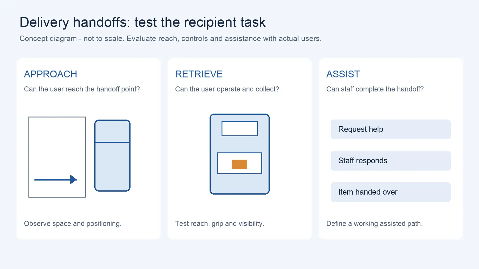
Delivery Robot Accessibility: Tray Reach, Controls, and Assisted Handoffs
Oct 12, 2026
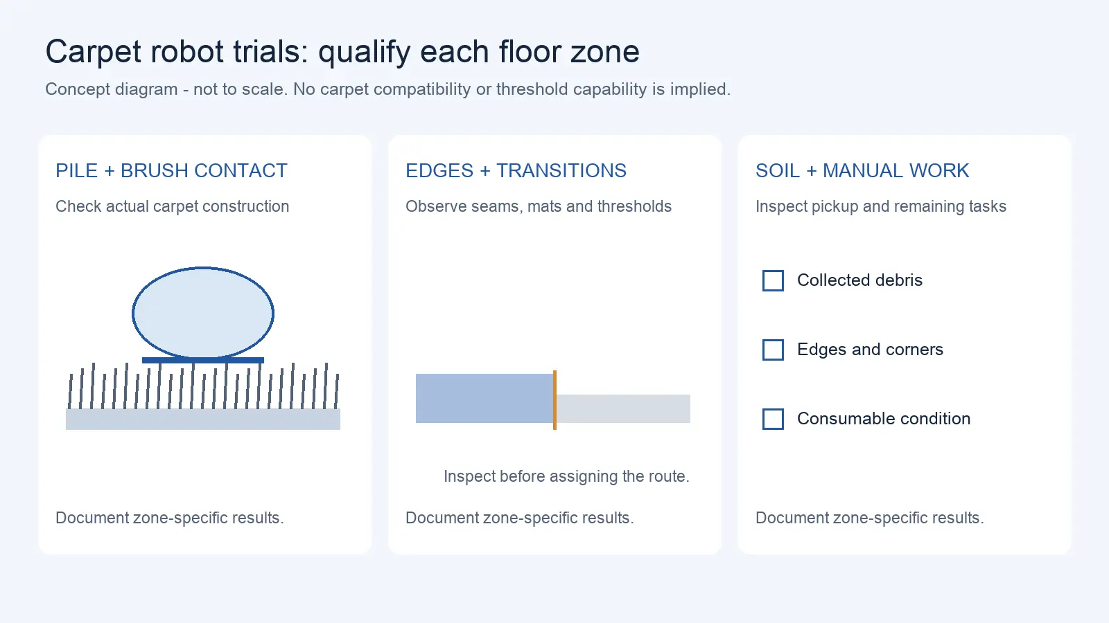
Commercial Carpet-Vacuuming Robots: Pile, Edge Transitions, and Maintenance Limits
Oct 12, 2026
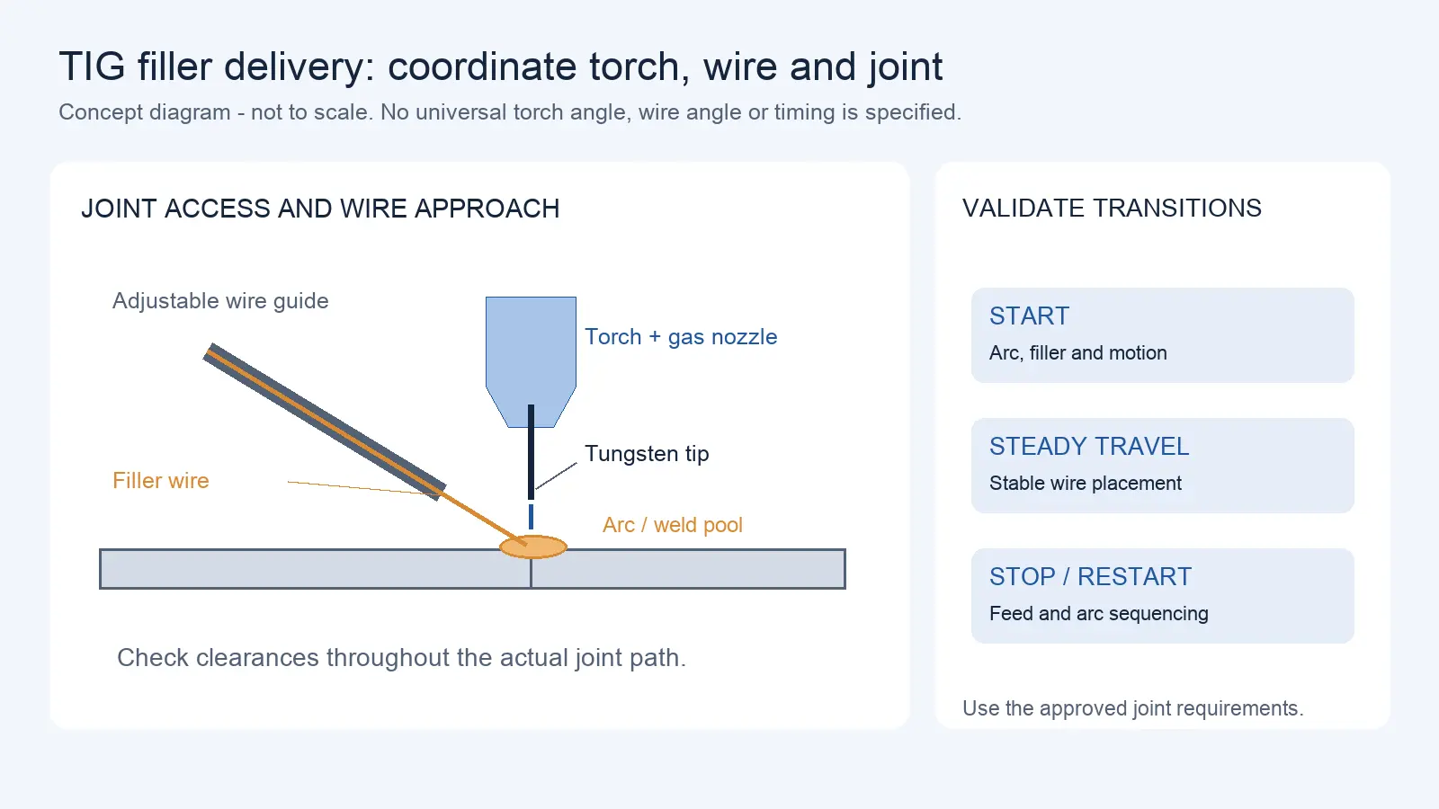
Robotic TIG Filler-Wire Delivery: Feed Angle, Arc Access, and Stop-Start Quality
Oct 12, 2026
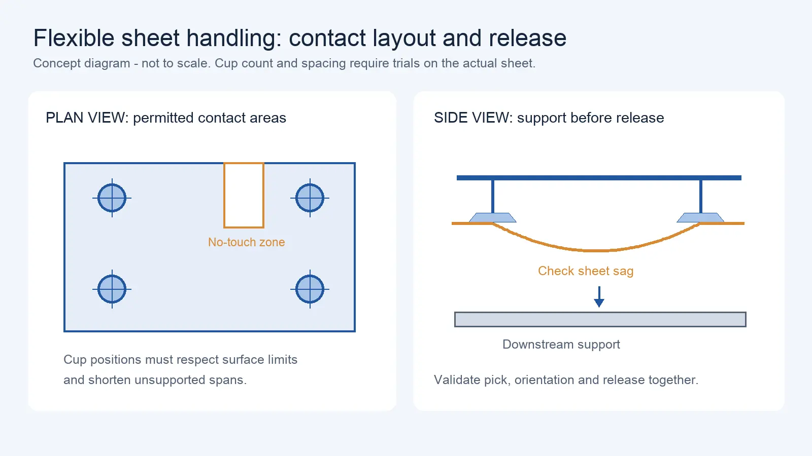
Suction Cup Layout for Flexible Sheets: Sag, Local Stress, and Controlled Release
Oct 12, 2026
An AMR base parks at a workstation with its navigation system reporting good positioning. The arm reaches for the part — and misses by several millimeters. The base did its job. The arm did its job. But the combined error budget exceeds what the task requires.
This is the core challenge of mobile manipulation: accuracy is not one number. It is a stack of independent error sources — base localization, docking repeatability, arm calibration, part pose estimation, fixture tolerance, and tool center point (TCP) offset — each contributing its own uncertainty. Understanding how these sources combine is essential for specifying, testing, and accepting a mobile manipulator.
Why Arm Repeatability Is Not Task Accuracy
A common specification confusion: the arm datasheet states a high repeatability value (e.g., a datasheet example), so the system should achieve that same value at the workpiece. This is rarely true in mobile manipulation.
Arm repeatability is measured under controlled conditions: fixed base, known load, consistent approach angle, stable temperature, and a test pin at a known position. In a real mobile manipulation task:
- The base is not rigidly bolted to a foundation — it sits on wheels or pads with compliance.
- The load and approach angle vary per task.
- The part position is not a test pin — it is estimated by vision or located by a fixture.
- Temperature and vibration differ from a lab.
Arm repeatability tells you the arm’s contribution to the error budget. It does not tell you the system’s task accuracy. System accuracy cannot be inferred from any single component specification — it may be dominated by one or more contributing factors depending on the task and configuration.
The Error Budget Stack
Mobile manipulation accuracy is a chain. Each link adds uncertainty:
| Error source | What it means | What determines it |
| Base localization | Where the AMR thinks it is vs. where it actually is | Navigation system, map quality, reference markers, environment |
| Docking repeatability | How precisely the base returns to the same position each time | Docking method (mechanical guide, marker, free navigation), floor conditions, approach speed |
| Base-to-arm transform | The geometric relationship between base frame and arm base frame | Mechanical mounting, calibration procedure, structural stiffness |
| Arm repeatability | How precisely the arm returns to a commanded pose | Arm drivetrain, backlash, encoder resolution, load |
| Part pose estimation | Where the vision system thinks the part is | Camera resolution, lighting, algorithm, part feature quality |
| Fixture tolerance | How precisely the fixture locates the part | Fixture design, wear, part variant |
| TCP offset | Where the tool tip actually is vs. where the controller thinks it is | Tool definition, tool change repeatability, wear |
How errors combine: These sources do not simply add linearly. In practice, some are systematic (repeatable bias) and some are random (statistical scatter). A first-order approach treats them as independent random sources and combines them as an RSS (root sum of squares) — but this is a simplification. Systematic errors from mounting offset or calibration drift can dominate and do not average out. The key takeaway: you cannot estimate system accuracy by looking at any one specification in isolation.
Base Localization and Docking: The Foundation of the Stack
The base contributes two distinct errors: localization accuracy (absolute position in the map) and docking repeatability (how consistently the base stops at the workstation).
Base localization:
- SLAM-based navigation provides a position estimate with uncertainty that depends on map quality, environment changes, and reference feature density.
- Marker-based docking (reflector, QR code, fiducial) can improve the final positioning significantly compared to free navigation.
- The localization error before docking becomes the starting point for the arm’s reach — if the base is off, the arm starts from the wrong place.
Docking repeatability:
- Free navigation docking (no mechanical guide) typically has higher scatter than marker-assisted or mechanical-pin docking.
- Mechanical docking guides (tapered pins, V-grooves, cones) can reduce base position variance but introduce their own requirements: floor flatness, guide wear, approach alignment tolerance.
- Docking on compliant floors (resilient tile, raised access floors) may introduce base tilt or settlement that affects the arm coordinate frame.
What to confirm: Ask the supplier for docking repeatability data measured under full-load conditions on the target floor type — not just on a test surface. If the supplier provides only localization accuracy, ask specifically about docking repeatability, which is the more relevant number for manipulation tasks.
Arm Calibration and Base-to-Arm Transform
Once the base is parked, the arm’s coordinate frame must relate to the base coordinate frame through a known transform. This transform is established by mechanical mounting and calibration.
Calibration factors:
- The mounting plate must be flat, rigid, and repeatable — any tilt or flex introduces a systematic offset that grows with arm reach.
- If the arm is remounted or serviced, the transform must be recalibrated — confirm the recalibration procedure and required tooling.
- Temperature changes affect arm length through thermal expansion; for precision tasks, this may matter.
Base-to-arm compliance:
- The arm base is not infinitely stiff relative to the AMR chassis. Under arm load, the mounting structure may deflect — this deflection is position-dependent and load-dependent.
- If the AMR uses stabilizing jacks or pads to reduce chassis compliance during manipulation, confirm their engagement sequence and whether the system verifies proper deployment before arm motion.
Part Pose Estimation: Vision, Fixtures, or Both
The arm needs to know where the part is. Three approaches are common:
| Approach | How it works | Error contribution | When it fits |
| Vision-based | Camera (mounted on arm or fixed) locates part features | Depends on camera resolution, working distance, lighting, algorithm, part feature quality | Parts with distinguishable features, controlled lighting |
| Fixture-based | Part is located by a mechanical fixture or nest | Fixture tolerance + part-to-fixture clearance | High-volume, consistent part geometry |
| Hybrid | Vision refines a coarse fixture position | Combined, typically lower than either alone | Precision tasks with part variability |
Vision challenges:
- Reflective or transparent parts defeat structured-light and stereo approaches.
- Lighting variation between shifts or stations changes feature contrast.
- Part presentation variability (orientation, height) requires the vision system to handle range, not just a fixed pose.
Fixture challenges:
- Fixture wear changes location over time — needs periodic verification.
- Part variants may not fit the same fixture — confirm fixture changeover time and accuracy impact.
- A fixture that locates the part but not the AMR still requires the base to dock precisely.
TCP Offset and Tool Change Repeatability
If the mobile manipulator uses interchangeable end-effectors (grippers, vacuum tools, specialized fixtures), the tool change mechanism contributes its own error.
- Tool change repeatability defines how precisely the tool returns to the same position relative to the arm flange after a change.
- TCP definition (where the controller believes the tool tip is) must match the physical tool — verify the TCP calibration procedure and whether it is manual or automatic.
- Tool wear changes the effective TCP over time — for high-precision tasks, periodic TCP verification is needed.
Error Budget Worksheet
Use this worksheet to assemble the error budget for your specific task. Fill in each value from supplier data, test results, or engineering estimates. Values without verified sources should be marked as estimates.
| Error source | Value (mm or deg) | Source | Notes |
| Base localization (pre-dock) | _____ | Supplier data or test | |
| Docking repeatability | _____ | Supplier FAT data on target floor | |
| Base-to-arm transform | _____ | Calibration certificate | |
| Base structural compliance under load | _____ | Supplier or test | |
| Arm repeatability | _____ | Arm datasheet (confirm test conditions) | |
| Part pose estimation | _____ | Vision supplier or fixture tolerance | |
| Fixture tolerance | _____ | Fixture design data | |
| TCP offset | _____ | Tool supplier or calibration | |
| Tool change repeatability | _____ | Tool changer datasheet | |
| Combined estimate | _____ | RSS or per your engineering analysis | Mark as estimate if any source is unverified |
This worksheet is an illustrative framework, not an industry benchmark. The actual error budget for your application depends on your specific equipment, environment, and task requirements.
FAT and SAT for Mobile Manipulation Accuracy
Factory Acceptance Testing (FAT):
- Test the combined system — base + arm + vision + tool — not just individual components.
- Use a test part with known position and verify the system can locate, approach, and contact it within the agreed tolerance.
- Repeat the test multiple times to measure scatter, not just a single best-case result.
- Test at different arm orientations and base approach angles — errors are not uniform across the workspace.
Site Acceptance Testing (SAT):
- Repeat the FAT protocol on the actual floor, with the actual part, fixture, and lighting.
- Test after the base has docked using the site’s docking method (marker, guide, or free navigation).
- Run the test across shifts or lighting conditions if vision is involved.
- Document the combined error and compare to the task tolerance — if the error budget exceeds the tolerance, identify which source contributes most and address it first.
Need to Check Mobile Manipulator Accuracy?
System accuracy depends on the full stack, not just arm repeatability. We can help review the required task tolerance against base docking, arm calibration, vision, fixtures, and tooling.
Please share, if available: required task tolerance, base docking method, part and fixture data, arm model, vision setup, tool or gripper details, and acceptance-test conditions.
Send Your Accuracy RequirementAccuracy Budget Decision Inputs
- Arm repeatability is not system accuracy — the error budget includes base, docking, calibration, vision, fixture, and TCP sources.
- Request combined system test data — not just arm or base specifications in isolation.
- Docking repeatability on your floor type matters more than localization accuracy — confirm the supplier tests under realistic conditions.
- The base-to-arm transform must be calibrated and verifiable — confirm the recalibration procedure after service.
- Part pose estimation error depends on your part and lighting — test with actual parts, not just supplier demo samples.
- Tool change repeatability contributes to TCP error — include it in the error budget if interchangeable tools are used.
- FAT and SAT must test the full stack — individual component tests do not predict system-level task accuracy.
Share on Social:


Contact Us
In This Article
Delivery Robot Accessibility: Tray Reach, Controls, and Assisted Handoffs
Oct 12, 2026
Commercial Carpet-Vacuuming Robots: Pile, Edge Transitions, and Maintenance Limits
Oct 12, 2026
Robotic TIG Filler-Wire Delivery: Feed Angle, Arc Access, and Stop-Start Quality
Oct 12, 2026
Suction Cup Layout for Flexible Sheets: Sag, Local Stress, and Controlled Release
Oct 12, 2026