

 Contact Us

 Home /
 Heavy-Duty AMR (1,500 kg+): Payload, Braking, Floor Load, Lifting, and Docking Acceptance
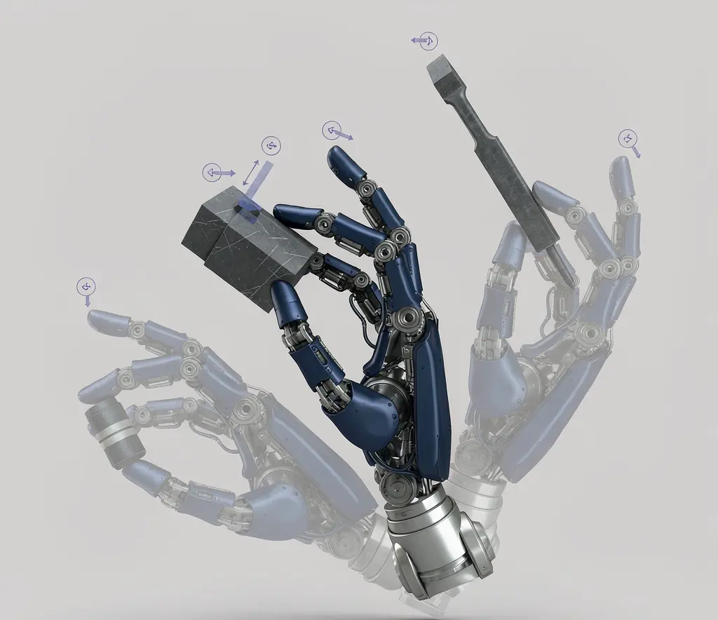
Humanoid Robot Hand Dexterity Verification: Grasp Set, Tool Use, Force Control, and Recovery
Oct 08, 2026

Industrial Exoskeleton Fit and Sizing: Anthropometry, Adjustment Time, PPE, and Shared-Device Programs
Oct 08, 2026

Robot Duty Cycle and Thermal Limits: Why Rated Payload and Speed Do Not Guarantee Continuous Operation
Oct 08, 2026

Robot IP Ratings Explained: What IP54, IP65, and IP67 Do — and Do Not — Prove
Oct 08, 2026
When payload goes from 500 kg to 1.5 tons, 3 tons, or even 5+ tons, the selection logic does not scale linearly.
Selecting a 500 kg AMR is mostly about payload margin, navigation method, and top module interface. At 1.5 tons and above, the focus shifts to structural stiffness, braking distance, floor bearing pressure, lift mechanism synchronization, load geometry stability, and safe recovery after failure. These are issues that rarely need separate attention in light-duty scenarios.
The reason is physics. Kinetic energy scales with mass and the square of velocity (E = ½mv²). A heavier robot at the same speed carries more energy. The concentrated load through each wheel contact patch can exceed what standard industrial flooring was designed for. If the load is not effectively constrained, emergency braking generates inertial force that shifts it forward, changing the CG and creating tipping risk.
The cost of getting it wrong is significant. If you reach acceptance testing and discover the floor cannot handle the load or braking distance falls short, the rework involves floor reinforcement, path redesign, or equipment replacement.
Load Geometry and Structural Stiffness Under Full Load
The core question for structural review is: under full load, does the robot chassis and lift mechanism deform enough to affect accuracy and safety?
The deformation chain:
- Chassis flex → wheel contact area changes → uneven traction and braking force → brake pull
- Lift mechanism deformation → load tilt → docking offset → CG shift → increased tipping risk
- Long-term full-load cycling → fatigue accumulation → fastener loosening → accelerated accuracy decay
Engineering parameters to confirm with the supplier:
| Review item | Why it matters | How to confirm |
| Max chassis deflection under full load (mm) | Excessive flex affects wheel pressure distribution and navigation accuracy | Request technical data or FAT measurement |
| Lift mechanism deformation under full load (mm) | Affects docking accuracy and load stability | FAT full-load lift test |
| Full-load fatigue cycling test data | Long-term accuracy decay expectation | Ask whether fatigue test data exists |
| Load constraint method | Prevents load shift during acceleration, braking, and ramps | Confirm mechanical constraint + sensor detection |
| Offset load allowable range | Real loads are never perfectly centered | Confirm max allowable offset ratio |
Do not accept structural parameters measured only under empty or light-load conditions. Heavy-duty AMR review must be based on full-load conditions — ideally with your actual load geometry and offset.
Braking, Stopping Distance, and Safe Speed Assumptions
The braking system is the core of heavy-duty AMR safety design.
Kinetic energy scales with mass and the square of velocity. A heavier AMR at the same speed carries more energy than a lighter one. Full-load stopping performance must be demonstrated for the configured vehicle and site conditions — do not assume braking distance from vehicle mass alone.
Several concepts need to be distinguished during procurement:
Rated braking distance: The distance the supplier tested under standard conditions — flat floor, specified floor material, full load, constant speed. This is a reference value.
Actual braking distance: The distance on your floor, with your load geometry, at your operating speed. Oil, ramps, offset loading, and high-CG loads all extend braking distance.
Safe speed: The maximum operating speed derived from actual braking distance and the longest sightline on the path. If the path has blind spots (turns, doorways, shelf ends), safe speed may be well below the rated maximum.
Braking risks specific to heavy-duty:
- Load surge: During emergency braking, if the load is not effectively constrained, inertial force shifts it forward relative to the robot, changing the CG and potentially causing the robot to pitch forward or the load to fall.
- Wheel load transfer: Braking shifts load to the front wheels and unloads the rear. On a differential chassis, the drive wheel may lose traction.
- Insufficient floor friction: Heavy-duty AMR exerts high wheel pressure. On oily or smooth floors, it is more likely to break static friction and enter a slide.
Ask the supplier for full-load braking distance test data and the floor conditions used. If your site floor has a lower friction coefficient than the test conditions, safe speed and braking distance need to be reassessed.
Floor Load: Wheel Contact Patch, Slab Joints, and Structural Assessment
Floor requirements for heavy-duty AMR go well beyond “flat and smooth.” Floor bearing capacity is the most underestimated constraint in heavy-duty deployment.
The floor assessment for heavy-duty AMR is not just a kN/m² number. What matters is the concentrated wheel load — the force transmitted through each wheel’s contact patch into the floor slab. That depends on wheel count, wheel diameter, tire material, and load distribution. A 3-ton AMR with four small wheels creates very different floor stress than the same weight on eight larger wheels.
Floor review checklist:
| Floor parameter | Why it matters for heavy-duty AMR | How to assess |
| Concentrated wheel load (kN per wheel) | Determines whether slab can withstand point load | Calculate from total mass, wheel count, and contact patch area |
| Slab thickness and joint design | Joints are the weakest points under heavy point loads | Check floor design specs or commission structural assessment |
| Joint width and height difference | Impact force at joints under heavy load | On-site measurement, log all joint locations |
| Ramp slope and length | Full-load climbing tests traction and braking limits | Measure all path ramps |
| Floor friction coefficient | Directly affects braking distance and ramp traction | Assess by actual floor material and contamination |
| Wheel configuration and contact area | Determines per-wheel pressure distribution | Confirm wheel specs and count |
If your floor bearing capacity is uncertain, do not assume “if others can use it, so can I.” Commission a structural assessment — the floor may need reinforcement before heavy-duty AMR deployment. This assessment should be performed by a structural or facilities engineer who can evaluate slab thickness, subgrade, joint design, and dynamic loading conditions.
Single-Point vs. Synchronized Lifting
The lift mechanism design directly affects load stability and docking accuracy.
Single-point lift: One lifting platform carries the entire load. Simpler structure, but with large or asymmetric loads, single-point lifting can cause platform tilt.
Synchronized lift: Multiple lifting points act in sync, distributing the load and reducing platform tilt. Better for large-area loads or docking scenarios with high levelness requirements. But the added complexity means more maintenance and more failure points.
The choice is not “synchronized is always better.” It depends on load geometry and docking requirements:
- Small load area, centered CG, low docking precision requirement → single-point may be sufficient
- Large load area, noticeable offset, high docking precision requirement → synchronized is more appropriate
- Exceptionally long or wide loads (automotive components, steel coils) → may need a custom lift solution
Ask the supplier to perform a full-load lift test during FAT and measure platform levelness deviation after lifting. If using synchronized lift, confirm the sync error range and the safety response when synchronization is lost (auto-lock, alarm, speed reduction).
Docking with Long, Wide, or Eccentric Carriers
Heavy-duty AMRs frequently handle non-standard load shapes — engine assemblies, battery packs, steel coils, large fixture frames. The geometry of these loads directly affects docking difficulty.
Long loads: Large turning sweep path. Narrow aisles and intersections need more safety margin. During docking, the front end of a long load may extend beyond the robot’s sensor range, requiring additional sensors or manual guidance.
Wide loads: Aisle width requirements may far exceed the robot body width. Both sides need clearance that accounts for load width plus passing traffic.
Eccentric loads: The CG is not at the robot’s geometric center. Turning produces asymmetric centrifugal force. Braking shifts the load in a direction that may not be straight ahead. Eccentric loads can also cause uneven wheel pressure, overloading one side.
Docking conditions to test during acceptance:
| Docking condition | Test focus | Pass criteria (define per project) |
| Full-load straight docking | Positioning accuracy, docking force, load stability | _____ |
| Full-load docking after turn | Position recovery after turn, load attitude change | _____ |
| Offset-load docking | Positioning deviation under offset | _____ |
| Ramp docking | Load stability during docking on slope | _____ |
| Repeat docking | Repeatability over consecutive cycles | _____ |
Battery, Thermal Load, and Full-Load Duty Cycling
The impact of heavy-duty operation on battery and thermal management is easy to underestimate.
Under full load, drive motor current rises significantly. Motors and drives heat up faster. If the robot runs continuously at full load (high duty cycle), thermal protection may trigger speed reduction or shutdown — something that never shows up in light-load demos.
Battery discharge curves also change under heavy load. High-current discharge causes voltage to drop faster. The actual runtime under full load may be shorter than the spec sheet’s rated runtime — which may be tested under lighter load conditions. The actual reduction depends on the load profile, battery chemistry, and BMS design.
What to confirm with the supplier:
- What load conditions and duty cycles were the runtime parameters tested under?
- At what temperature threshold does thermal protection trigger during full-load continuous operation? How does the robot respond?
- What is the duty cycle limit under full-load conditions? Is forced cooling downtime required?
Heavy-Duty AMR Acceptance Test Checklist
Use this checklist during FAT (factory acceptance testing) and SAT (site acceptance testing) to systematically verify engineering performance.
| Test category | Test item | Test conditions | Pass criteria (define per project) | FAT/SAT |
| Full-load operation | Full-load straight travel | Actual max load, specified speed | _____ | FAT+SAT |
| Full-load turning | Actual max load, specified turn radius | _____ | FAT+SAT | |
| Full-load ramp climbing | Actual max load, path max slope | _____ | FAT+SAT | |
| Offset load test | Offset straight travel | Max allowable offset condition | _____ | FAT |
| Offset turning | Max allowable offset condition | _____ | FAT | |
| Braking test | Full-load emergency stop | Actual max load, specified speed, actual floor | _____ | FAT+SAT |
| Full-load ramp holding | Actual max load, path max slope | _____ | FAT+SAT | |
| Lift test | Full-load lift | Actual max load | _____ | FAT |
| Full-load lift hold | Actual max load, hold after lifting | _____ | FAT | |
| Docking test | Full-load straight docking | Actual max load, actual docking interface | _____ | FAT+SAT |
| Full-load docking after turn | Actual max load, docking after turn | _____ | SAT | |
| Thermal test | Full-load continuous run | Actual max load, continuous run for specified duration | _____ | FAT |
| Full-load duty cycling | Actual max load, specified work cycle | _____ | FAT | |
| Floor test | Actual floor operation | Actual load, actual route floor | _____ | SAT |
| Exception recovery | Full-load fault recovery | Simulated fault, recovery operation | _____ | SAT |
Planning a Heavy-Duty AMR Project?
Heavy payloads need more than a payload number. We can help review braking, concentrated floor load, load geometry, lifting, docking, and recovery requirements before you shortlist a platform.
Please share, if available: maximum load, load dimensions and CG, fixture weight, floor or slab information, ramps, docking points, duty cycle, and site constraints.
Request Heavy-Duty EvaluationHeavy-Duty Acceptance Inputs
- Do not apply light-duty selection logic to heavy-duty — the core review for heavy-duty AMR is structure, braking, floor, and lifting, not the payload number.
- Floor assessment goes beyond kN/m² — evaluate concentrated wheel load, slab thickness, joint design, and dynamic conditions. Commission a structural engineer if needed.
- Full-load braking distance is the safety baseline — require supplier full-load brake test data and assess against your actual floor conditions.
- Lift mechanism deformation and levelness under full load must be FAT-verified — do not settle for empty-load lift demos.
- Offset and long/wide load docking tests are not optional — real load geometry is almost never perfectly centered.
- Thermal load and duty cycle under full-load conditions must be tested — light-load demos will not expose thermal protection issues.
- Exception recovery plans must be confirmed during procurement — how to safely remove the robot and load after a full-load failure is not something to figure out after the fact.
Share on Social:


Contact Us
In This Article
Humanoid Robot Hand Dexterity Verification: Grasp Set, Tool Use, Force Control, and Recovery
Oct 08, 2026
Industrial Exoskeleton Fit and Sizing: Anthropometry, Adjustment Time, PPE, and Shared-Device Programs
Oct 08, 2026
Robot Duty Cycle and Thermal Limits: Why Rated Payload and Speed Do Not Guarantee Continuous Operation
Oct 08, 2026
Robot IP Ratings Explained: What IP54, IP65, and IP67 Do — and Do Not — Prove
Oct 08, 2026