

 Contact Us

 Home /
 AMR Payload Rating vs. Real Load: How to Calculate Load Center, Tare Weight, and Dynamic Forces
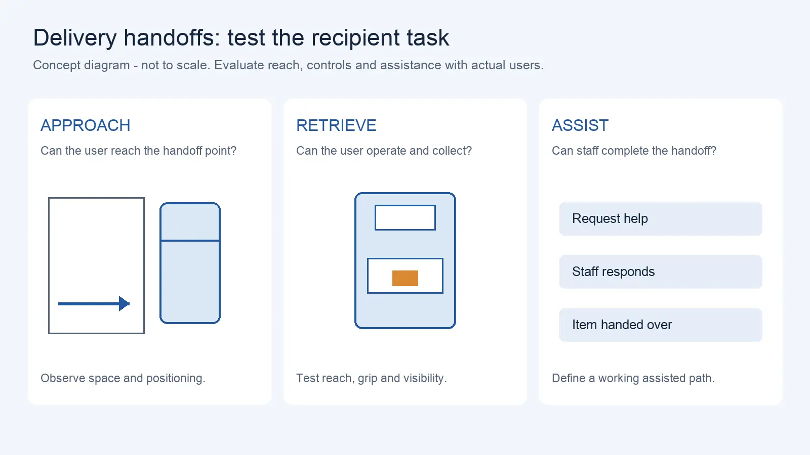
Delivery Robot Accessibility: Tray Reach, Controls, and Assisted Handoffs
Oct 12, 2026
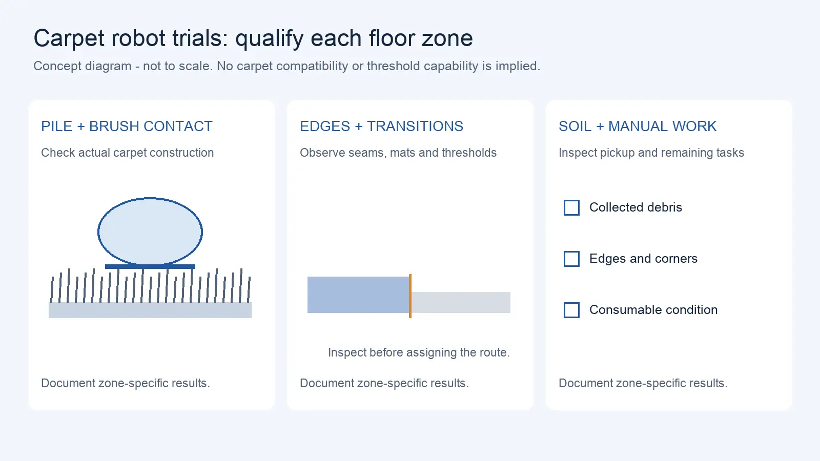
Commercial Carpet-Vacuuming Robots: Pile, Edge Transitions, and Maintenance Limits
Oct 12, 2026
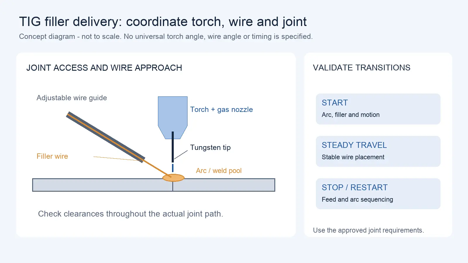
Robotic TIG Filler-Wire Delivery: Feed Angle, Arc Access, and Stop-Start Quality
Oct 12, 2026
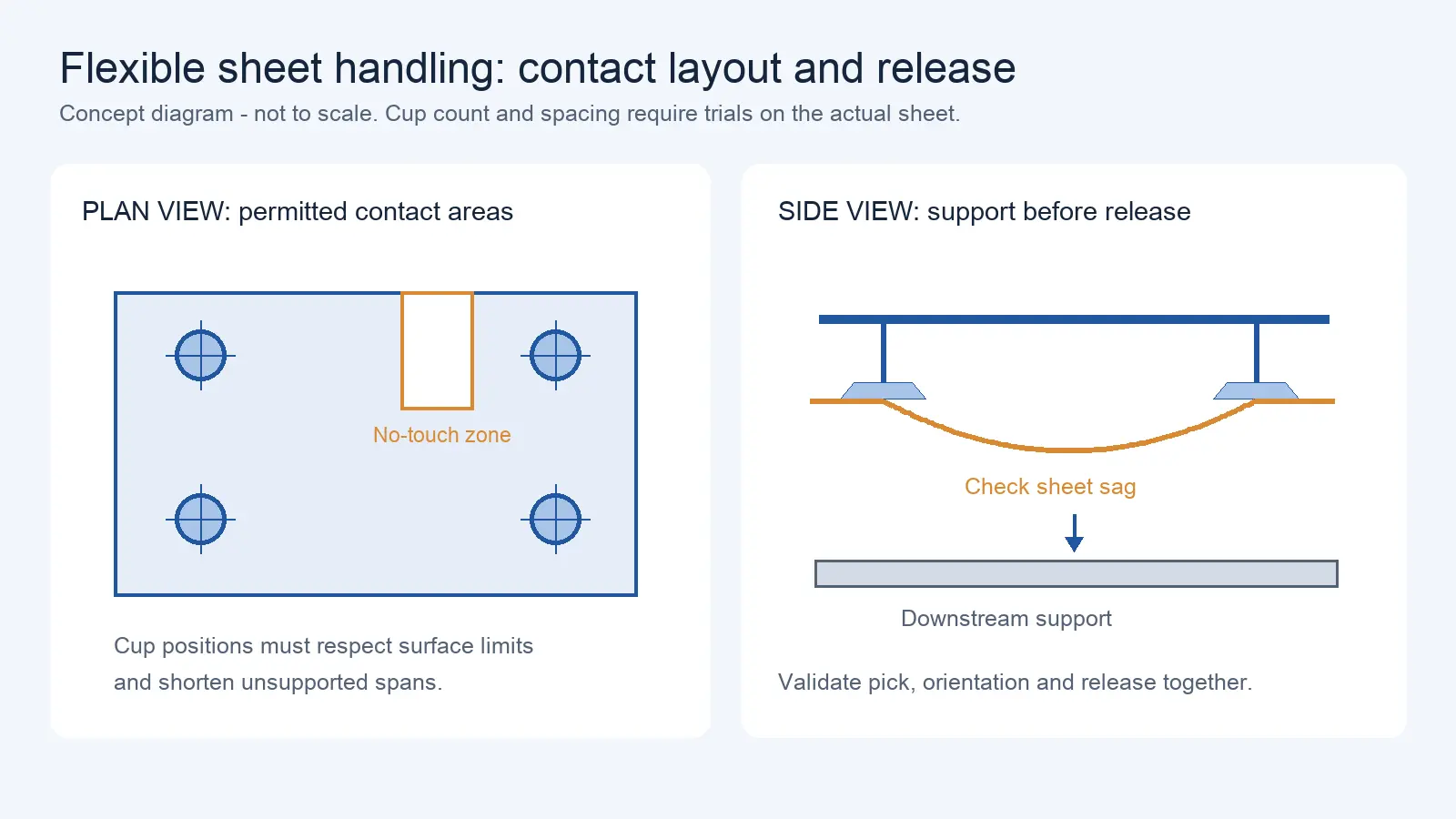
Suction Cup Layout for Flexible Sheets: Sag, Local Stress, and Controlled Release
Oct 12, 2026
An RFQ lands on a supplier’s desk: “Need an AMR that carries 500 kg, 16 hours a day, ramp access, oily floor in machining area.” The supplier quotes a robot rated at 500 kg payload. The buyer checks the number against their heaviest pallet and moves on.
Four months later, at site acceptance, the robot carries the load — but overshoots braking distance on the ramp, slips near the CNC zone, and misses docking alignment when the pallet is offset. The buyer asks for a fix. The supplier asks: what is your actual total moving mass, load center distance, and ramp angle?
The gap between rated payload and real load is where most AMR selection problems hide. Rated payload is a manufacturer-defined value under stated configuration and test conditions — which may include assumptions about floor flatness, speed, load distribution, and center of gravity position. These conditions are specific to that manufacturer and model, not an industry-unified definition. In real operations, pallets, carts, and top modules add weight. The load center is rarely at the geometric center. The robot accelerates, brakes, turns, climbs ramps. Every one of these factors changes what that number means on your floor.
Calculating Total Moving Mass: Cargo + Carrier + Top Module
The first step in selection is not checking how much the robot can carry. It is figuring out the total mass you need it to move — and then mapping that mass to the manufacturer’s payload definition.
Start by listing every mass component in your application:
| Mass component | What it is | What to confirm with supplier |
| Cargo net weight | The product or material being transported | Buyers usually focus only on this number |
| Pallet/cart/fixture weight | The carrier that holds the cargo | Provide your actual pallet/cart weight — do not assume a generic range |
| Top module self-weight | The lift, roller, or custom fixture mounted on the AMR | Ask: does rated payload already exclude module self-weight? |
| Offset load additional force | Force generated by load center offset | Does not show up as mass but affects structure |
| Dynamic force | Inertial force from acceleration/deceleration and ramps | Instantaneously increases effective payload demand |
Before comparing your total to the rated payload, confirm the manufacturer’s payload definition: does it include or exclude the top module? Is the module part of the vehicle’s configured mass (tare) or counted against payload? Different manufacturers use different conventions — do not assume a single rule.
Here is an illustrative example (not an industry benchmark). You need to move a pallet of goods. Cargo weighs 400 kg. The pallet adds 20 kg. The robot has a lift-top module that weighs 30 kg. If the manufacturer’s rated payload excludes module self-weight, your cargo + pallet = 420 kg against a 500 kg rating, with 80 kg headroom. If the manufacturer includes the module in the vehicle tare, the same 420 kg applies. But if the manufacturer counts the module against payload, your total payload demand is 450 kg — and the headroom shrinks to 50 kg.
Ask the supplier how the configured top module is treated in that model’s payload definition. Compare cargo, carrier, fixture, and module mass against the OEM’s stated payload/tare convention; do not add or subtract module mass until that convention is confirmed.
Load Center, Overhang, and Center of Gravity Height
Payload is not just about weight. It is about where that weight sits. The same 500 kg load with its center of gravity at the robot’s geometric center versus offset by 200 mm has completely different effects on the robot.
Load center is the distance from the load’s center of gravity to the robot’s load-bearing reference point. The farther the load center, the greater the torque the same weight produces, and the lower the robot’s effective carrying capacity. This principle is identical to the load center concept in forklift selection — but many AMR buyers do not carry over that knowledge from forklift experience.
Three geometric parameters to confirm:
Load center distance: The horizontal distance from the load’s center of gravity to the robot’s reference point. Offset loading, asymmetric pallet placement, and cart center-of-gravity offset all change this value.
Overhang: The portion of the load that extends beyond the robot’s load-bearing surface edge. Overhang does not add vertical load, but it changes torque distribution and affects turning sweep path and stability.
Center of gravity height: The height of the load’s center of gravity from the ground. A high-CG load generates larger overturning torque during turns and braking. Even if the weight is within rated payload, a high CG can trigger stability limits.
These parameters matter because the rated payload is typically based on a standardized load geometry — evenly distributed, CG at the center of the load surface, CG height at a reference value. Your actual load geometry will almost never match this standard condition exactly.
Acceleration, Braking, Ramps, and Dynamic Load Transfer
Being able to carry 500 kg statically does not mean the robot can operate safely with that load in dynamic conditions.
When the robot accelerates or brakes, inertial forces instantaneously increase the effective payload demand. During braking, the forward tipping torque is proportional to the load center distance and CG height. A 400 kg load with a high CG and a long load center can produce more overturning torque during emergency braking than a 500 kg load with a low CG and a short load center.
Ramps make this more direct. On an incline, the slope angle shifts the effective gravity component rearward (uphill) or forward (downhill), changing wheel loading. The actual impact depends on the slope angle, load geometry, speed, and floor friction — these must be verified for your specific ramp and load conditions, not assumed from a generic threshold.
Floor conditions amplify these effects. Oil on the floor reduces friction, extending braking distance and causing ramp slippage. Floor gaps and height differences cause impact loads — the instantaneous force depends on the gap geometry, speed, and load. Do not assume a fixed multiplier; test on your actual floor.
What to verify: Rated payload does not tell you what the braking distance will be on your floor, at your ramp angle, with your actual load geometry. It does not tell you whether the wheels will slip or whether the robot will downshift speed during turns. These can only be verified through on-site testing or simulation.
Why a Flat Payload Margin Percentage Does Not Work
Many buying guides suggest “leave 20% payload margin” or “use 80% of rated capacity.” This advice sounds prudent but masks the real issue.
Twenty percent margin for what scenario? A robot with 500 kg rated payload, used at 80%, means operating at 400 kg. If your cargo + pallet + module totals exactly 400 kg, the CG is centered, the floor is flat, there are no ramps, and the robot runs at constant speed — that margin might be enough.
But if your load CG is 200 mm high, the floor has a slope, the path has speed bumps, and pallets are routinely offset — 20% may fall far short. On the other hand, if your load CG is low, the floor is smooth, the path is straight, and operating speed is low — 20% may be overly conservative, wasting the robot’s capacity.
The right approach is not to apply a flat percentage. Give your actual operating parameters to the supplier and let them provide an engineering assessment based on load geometry, dynamic conditions, and floor status. If the supplier responds with “our robot carries 500 kg, that’s enough” without asking about your load geometry and operating conditions, that response is itself a red flag.
How Floor Conditions and Wheel Layout Change Available Payload
How much a robot can carry depends not only on the robot and the load, but also on the floor and the wheels.
The same 500 kg rated AMR on smooth epoxy flooring versus an oily, wet, metal-chip-laden factory floor may have significantly different available payload. The robot has not changed — the floor’s friction coefficient has dropped, limiting traction and braking force. The system software may proactively reduce speed or limit payload when it detects wheel slip. The actual reduction depends on the floor condition and the robot’s traction control — do not assume a fixed percentage.
Wheel layout matters just as much. Different chassis architectures distribute load differently under offset loading. Confirm how the specific vehicle’s drive wheel position, caster arrangement, and load-bearing geometry handle your actual load center — do not generalize from one chassis type to another.
A four-wheel omnidirectional layout (such as Mecanum wheels) experiences changes in contact area and friction direction during lateral movement. Available payload in sideways motion may be lower than the rated value for forward/backward motion. This means the same robot might carry 500 kg moving forward but only safely handle a lower figure moving sideways — whether the spec sheet distinguishes between these matters, and many do not.
Ask the supplier which direction of travel, which floor condition, and which wheel configuration the rated payload is based on. If the spec sheet gives only one number, request payload data under different conditions.
Payload Verification Worksheet: For RFQ and FAT/SAT Stages
Use this worksheet during procurement inquiry and factory/site acceptance testing to systematically verify whether the robot’s payload capacity matches your actual operating conditions.
Payload Verification Worksheet
| Verification item | Buyer fills in | Supplier confirms | Acceptance test method |
| Total moving mass | |||
| Cargo net weight (kg) | _____ | Confirm whether rated payload includes module self-weight | Weighing record |
| Pallet/cart/fixture weight (kg) | _____ | — | Weighing record |
| Top module self-weight (kg) | _____ | Provide module technical parameters | Technical documentation |
| Total moving mass (kg) | _____ | Confirm whether within rated payload range | Calculation |
| Load geometry | |||
| Load center distance (mm) | _____ | Provide standard load center for rated payload | Technical documentation |
| Load CG height (mm) | _____ | Confirm maximum allowable CG height | Technical documentation |
| Overhang (mm, each direction) | _____ | Confirm maximum allowable overhang | Technical documentation |
| Offset loading description | _____ | Confirm payload reduction under offset conditions | FAT offset test |
| Dynamic conditions | |||
| Max travel speed (m/s) | _____ | Confirm max speed at full load | Speed test |
| Acceleration (m/s²) | _____ | Confirm acceleration at full load | Acceleration test |
| Deceleration/braking distance (m) | _____ | Confirm braking distance at full load | Brake test |
| Max path slope (°) | _____ | Confirm ramp climbing at full load | Ramp test |
| Path floor type | _____ | Confirm floor friction coefficient requirements | Floor assessment |
| Wheels and floor | |||
| Wheel layout | _____ | Confirm payload capacity by direction of travel | Directional payload test |
| Floor flatness description | _____ | Confirm floor requirements | Floor measurement |
| Oil/water/debris conditions | _____ | Confirm environmental limits | Site inspection |
| Acceptance criteria | |||
| FAT full-load test result | — | Provide test report | Full-load operation test |
| FAT offset-load test result | — | Provide test report | Offset-load operation test |
| FAT brake test result | — | Provide test report | Full-load braking distance measurement |
| FAT ramp test result | — | Provide test report | Full-load ramp climbing test |
| SAT on-site full-load run | — | On-site verification | Actual load + actual route operation |
Need Help Verifying the Real AMR Load?
Send the real load case before choosing a payload rating. We can help compare the robot specification against the mass, geometry, route, and floor conditions that matter on-site.
Please share, if available: cargo weight, carrier or fixture weight, top-module configuration, load-center or CG information, ramps, floor condition, and target duty cycle.
Send Your Load DataWhat to Ask the Supplier Before Ordering
- Rated payload test conditions — what load geometry, floor type, speed, and slope were used to derive the rated payload number?
- Included module — does rated payload already exclude the top module’s self-weight?
- Permitted CG envelope — what is the maximum allowable load center distance and CG height?
- Speed derating — at what load or condition does the robot automatically reduce speed?
- Slope capability — what is the maximum ramp angle at full load, and what is the braking distance on that slope?
- Braking evidence — can the supplier provide full-load braking distance test data on a floor similar to yours?
- Run full-load + offset-load + braking + ramp tests during FAT — do not settle for an empty-load demo.
- Run SAT with your actual load on your actual route — this is the only test that verifies the robot’s real capability under your operating conditions.
Share on Social:


Contact Us
In This Article
Delivery Robot Accessibility: Tray Reach, Controls, and Assisted Handoffs
Oct 12, 2026
Commercial Carpet-Vacuuming Robots: Pile, Edge Transitions, and Maintenance Limits
Oct 12, 2026
Robotic TIG Filler-Wire Delivery: Feed Angle, Arc Access, and Stop-Start Quality
Oct 12, 2026
Suction Cup Layout for Flexible Sheets: Sag, Local Stress, and Controlled Release
Oct 12, 2026