

 Contact Us

 Home /
 Robot Vision Lighting for Reflective, Dark, and Variable Parts: What to Test Before Deployment

Central Vacuum Pump vs On-Tool Ejector: Choosing the Vacuum Source for Robotic Picking
Oct 11, 2026

AMR Tugger Tow Capacity: Drawbar Pull, Cart Resistance, and Starting Loads
Oct 11, 2026
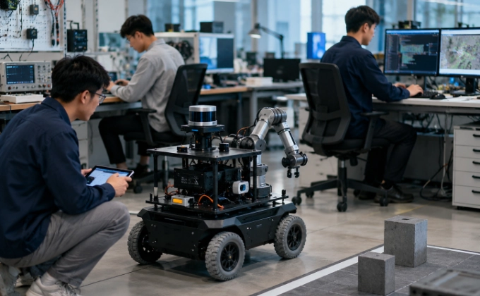
Robotics Teaching Labs: Specify the Student Exercises Before Choosing the Hardware
Oct 11, 2026

SCARA, Delta, or Six-Axis Robot: Choose by Motion, Orientation, and Work Envelope
Oct 11, 2026
The following scenario is illustrative and does not represent data from any specific deployment. A vision system is installed on a robot cell to identify parts on a conveyor. In the supplier's demo, the system achieves 99% recognition accuracy. In production, the accuracy drops to 85%. The difference is not the camera or the algorithm. It is the lighting. The demo used uniform matte parts under controlled studio lighting. Production uses parts with varying surface finish, oil residue, color variation, and ambient light from skylights and welding flashes. The camera that looked perfect in the demo cannot cope with the real-world conditions because the lighting was never tested against the worst-case parts in the worst-case environment. This article covers how to design and verify robot vision lighting so that the system works on the actual parts in the actual factory, not just in the demo room.
Light Reveals Features That Pixels Alone Cannot
A machine vision system captures images, but the information in those images is determined by the interaction of light, optics, part surface, and camera. Increasing camera resolution does not recover information that was never captured because the lighting failed to create contrast. If a shiny metal part reflects the light source directly into the camera lens, the image is saturated and no amount of pixels will reveal the feature. If a dark part absorbs most of the light, the image is too dark for the algorithm to detect edges.
Lighting is the element that creates the contrast between the feature of interest and the background. The choice of lighting geometry, wavelength, polarization, and intensity determines what features are visible. No camera or algorithm can extract information that the lighting failed to produce.
Characterize Worst-Case Surface Conditions
Before selecting lighting, the team must characterize the range of surface conditions the vision system will encounter. This includes:
- Glossy vs matte: Parts with high-gloss finish reflect light specularly, creating hot spots. Matte finish scatters light, providing more diffuse illumination but lower contrast for surface features.
- Dark vs light colors: Dark parts absorb more light, requiring higher intensity or longer exposure. Light parts reflect more, potentially causing saturation.
- Transparent or translucent materials: These interact with light in complex ways, creating internal reflections and refractions.
- Metallic surfaces: Reflective surfaces can act as mirrors, creating false features or hiding real ones.
- Oil, water, or coolant residue: These change the surface reflectance and may create patterns that the algorithm interprets as features.
- Labels and printing variation: Batch-to-batch variation in label position, print quality, or color can confuse feature-based algorithms.
- Wear and damage: Scratches, dents, and corrosion change the surface characteristics and may create false features.
The team should collect physical samples representing the best-case, typical, and worst-case conditions. Photographs of these samples under the proposed lighting should be compared to identify which conditions create the most difficulty for the vision system.
Reflective or damaged pallet surfaces create similar inspection questions in autonomous forklift pallet detection and docking, although their acceptance criteria are different.
Lighting Geometry: Backlight, Dark Field, Dome, and Coaxial
Different lighting geometries reveal different features:
- Backlight: Light from behind the part, creating a silhouette. Best for outline and dimensional measurement. Does not reveal surface features.
- Dark field: Light at a shallow angle to the surface. Reveals surface defects, scratches, and engravings by creating shadows from surface variations. Does not illuminate flat specular surfaces.
- Dome (diffuse): Light from all directions using a hemispherical diffuser. Eliminates specular reflections and provides uniform illumination on curved and shiny parts. Good for general inspection but may wash out fine surface features.
- Coaxial: Light along the camera axis, reflected through a beam splitter. Reveals flat reflective surfaces and surface features on mirrored parts. Not suitable for curved parts where the reflection does not return to the camera.
Contours vs surface defects
The choice of geometry depends on what needs to be measured. If the task is to locate the part and measure its outline, backlight or a structured front light may be sufficient. If the task is to detect surface defects (scratches, dents, porosity), dark field or a specialized grazing-angle light is needed. If the task is to read a code or verify a label, a dome or coaxial light may provide the most consistent results.
No single geometry works for all features. A system that needs to measure both outline and surface defects may require multiple lighting configurations, either with multiple light sources or with a configurable light that can switch geometries.
Polarization, Wavelength, and Spectral Response
Polarization can reduce or eliminate specular reflections from shiny surfaces. A polarizer on the light source and a crossed polarizer on the camera lens can suppress reflections that would otherwise saturate the image. This is particularly useful for inspecting glossy metal, plastic, or glass parts.
Wavelength selection can enhance contrast for specific features. Ultraviolet (UV) light can cause certain materials to fluoresce, revealing features invisible under white light. Infrared (IR) light can penetrate some materials and reveal subsurface features. Colored filters can enhance the contrast between features of different colors.
The effectiveness of polarization and wavelength selection depends on the specific material and surface. These techniques should be tested with actual parts, not assumed from general principles. A polarizer that eliminates reflections on one material may have no effect on another.
Ambient Light, Flicker, and Shift Variation
In a factory environment, ambient light is rarely controlled. Sources of ambient light variation include:
- Skylights and windows: Daylight changes with time of day, weather, and season
- Overhead lighting: Fluorescent and LED fixtures may flicker at frequencies that interfere with camera exposure
- Welding arcs: Intense, intermittent light that can saturate the camera and trigger false detections
- Adjacent equipment: Indicator lights, displays, and process illumination from nearby machines
If the vision system is affected by ambient light, the solution is either to shield the inspection area (enclosures, light-tight covers) or to use lighting that is intense enough to overwhelm the ambient contribution. Strobe lighting, synchronized with the camera exposure, can provide high-intensity illumination that makes ambient light negligible.
The worst-case ambient condition must be identified and tested. If the system works at night but fails when the skylights let in afternoon sun, the system is not production-ready.
Welding seam tracking methods present a process-specific sensing comparison; this article addresses illumination variability across machine vision applications.
Robot Speed, Exposure, and Motion Blur
If the part or the robot is moving during image capture, the exposure time must be short enough to freeze the motion. Motion blur occurs when the part moves more than one pixel during the exposure. The amount of blur depends on the speed, the exposure time, and the field of view.
To reduce motion blur:
- Strobe lighting: A brief, high-intensity flash that effectively freezes motion. The strobe duration must be short enough that the part moves less than one pixel during the flash.
- Increased intensity: Higher light intensity allows shorter exposure times, reducing blur. But higher intensity may cause saturation on reflective surfaces.
- Robot pause: The robot stops or slows during image capture. This eliminates motion blur but adds cycle time.
- Trigger and synchronization: The camera exposure is triggered at a specific point in the robot's motion, ensuring consistent capture conditions.
Trigger and strobe timing
In high-speed applications, the timing of the strobe, the camera trigger, and the robot motion must be synchronized. The robot controller sends a trigger signal at the defined position, the camera opens its shutter, and the strobe fires, all within a tightly controlled timing window. If any of these is misaligned, the image may be captured at the wrong position or with motion blur. The timing requirements should be specified and tested during commissioning.
2D/3D Illumination Constraints Without Reopening Architecture
This article assumes that the camera and vision architecture (2D or 3D) has been selected. The companion article “2D vs 3D robot vision” covers that selection. Here, the focus is on lighting, but it is worth noting that 2D and 3D systems have different lighting requirements. A 3D structured-light system projects a pattern onto the part, and the pattern's deformation reveals the 3D shape. Ambient light can interfere with the projected pattern, so 3D systems often require more controlled lighting or higher pattern intensity than 2D systems. A 3D stereo system uses two cameras and does not project a pattern, but it still requires adequate illumination for both cameras to capture features.
A Worst-Case Vision Test Matrix
Before approving a vision system for production, a test matrix should be executed that covers the full range of expected conditions:
| Part Variant | Surface Condition | Pose | Lighting | Robot Speed | Result |
|---|---|---|---|---|---|
| Part A (nominal) | Clean, matte | Nominal | Dome | Static | Pass |
| Part A (worst) | Oil residue | Tilted 5° | Dome | 200 mm/s | TBD |
| Part B (dark) | Clean, dark | Nominal | Dome + polarizer | Static | TBD |
| Part B (worst) | Scratch, oil | Tilted 5° | Dome + polarizer | 200 mm/s | TBD |
| Part C (shiny) | Clean, glossy | Nominal | Dark field | Static | TBD |
| Part C (worst) | Fingerprints | Tilted 5° | Dark field | 200 mm/s | TBD |
The matrix should be filled in with actual test results, including recognition confidence, retry count, and failure modes.
Failed-image evidence
The test matrix should include not only pass results but also failed images. Failed images (where the system could not identify the part, misidentified it, or returned low confidence) are more valuable for debugging than pass images. They reveal the conditions under which the system fails, which is the information needed to improve the lighting or the algorithm.
The team should save a library of failed images from commissioning and early production, annotated with the conditions that produced them. This library becomes the reference for evaluating whether changes to lighting, optics, or algorithm improve the worst-case performance.
Vision Approval and Change-Control Questions
Before approving the vision system, the buyer should confirm:
- Sample images: Best, typical, and worst-case images are documented and available for reference
- Lighting BOM: The exact lighting components (model, quantity, position, angle) are documented
- Calibration: The lighting is calibrated and the calibration procedure is documented
- Environmental limitations: The conditions under which the system is qualified (ambient light range, temperature, part surface range) are stated
- Maintenance and replacement: Lamp or LED replacement intervals, cleaning procedures, and recalibration triggers are defined
- Tuning responsibility: Who is responsible for adjusting parameters if part variants change or performance degrades
- Failure package: What happens when the vision system fails to identify a part (reject, retry, manual inspection, alarm)
EMVA 1288, the European Machine Vision Association's standard for characterizing image sensors and cameras, defines measurement methods for sensitivity, linearity, noise, and dark current. The current version is 4.0. It is useful for comparing camera specifications on a common basis and for understanding imaging terminology. It does not, however, prove that a specific application will achieve a specific recognition rate. Recognition performance depends on the entire system (lighting, optics, camera, algorithm, part, environment), not just the camera's EMVA 1288 characteristics.
Evaluating vision-guided automation on reflective, dark or variable parts? Share real part photographs or samples, the feature to detect, production lighting changes, camera/robot movement and target cycle time. AIsirRobot can help organize a preliminary application review and identify what the manufacturer or integrator must test under representative conditions.
Share on Social:


Contact Us
In This Article
Central Vacuum Pump vs On-Tool Ejector: Choosing the Vacuum Source for Robotic Picking
Oct 11, 2026
AMR Tugger Tow Capacity: Drawbar Pull, Cart Resistance, and Starting Loads
Oct 11, 2026
Robotics Teaching Labs: Specify the Student Exercises Before Choosing the Hardware
Oct 11, 2026
SCARA, Delta, or Six-Axis Robot: Choose by Motion, Orientation, and Work Envelope
Oct 11, 2026