

 Contact Us

 Home /
 Industrial Robot Foundation and Base Mounting: Flatness, Anchoring, Stiffness, and Vibration
Central Vacuum Pump vs On-Tool Ejector: Choosing the Vacuum Source for Robotic Picking
Oct 11, 2026

AMR Tugger Tow Capacity: Drawbar Pull, Cart Resistance, and Starting Loads
Oct 11, 2026
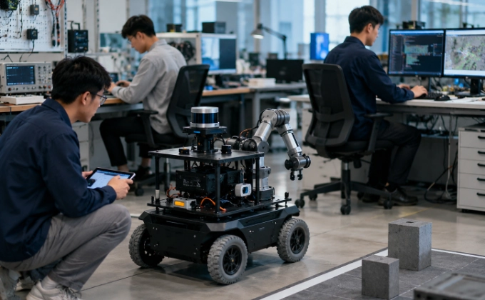
Robotics Teaching Labs: Specify the Student Exercises Before Choosing the Hardware
Oct 11, 2026

SCARA, Delta, or Six-Axis Robot: Choose by Motion, Orientation, and Work Envelope
Oct 11, 2026
An industrial robot is only as stable as the structure beneath it. When a robot exhibits positioning errors, vibration, or inconsistent cycle times, the first assumption is often that the robot controller needs tuning or the mechanical linkages have wear. In practice, the root cause may be the foundation. A base that is not flat, not stiff enough, or not properly anchored will deflect under dynamic loads, transmitting that deflection into the robot as positioning error. This article covers what buyers need to verify before the robot is bolted down, from manufacturer-specific mounting data through post-installation checks.
Why the Robot Base Is Part of the Motion System
A robot is a dynamic mechanical system. When it accelerates and decelerates a payload, the reaction forces do not disappear. They pass through the robot's base, into the pedestal or mounting structure, and into the floor. If that structure is not stiff enough to resist those forces, it deflects. That deflection changes the robot's position relative to the workpiece, introducing error that the robot controller cannot compensate for because the controller does not measure base deflection.
The same principle applies to vibration. A robot that vibrates at its base may be experiencing resonance between its motion frequencies and the natural frequency of the mounting structure. The robot is functioning correctly, but the structure is amplifying its motion. The solution is not to retune the robot but to stiffen the structure or change its mass distribution.
Understanding this means treating the base, pedestal, and foundation as part of the motion system, not as a passive support. The stiffness and stability of the mounting directly affect the robot's effective accuracy and repeatability.
Robot repeatability versus accuracy explains the performance terms, while this article addresses mounting-induced movement and vibration.
Start With Manufacturer-Specific Mounting Data
Every robot model has specific mounting requirements defined by the manufacturer. These requirements are not generic. They depend on the robot's payload, reach, mass, center of gravity, and the dynamic moments generated during operation. The buyer must obtain the manufacturer's installation data for the specific robot model and mounting orientation before designing or verifying the foundation.
The manufacturer's mounting data typically includes:
- Footprint and bolt pattern: The locations and sizes of the mounting bolts, and the required flatness of the mounting surface
- Mass and center of gravity: The robot's weight and the location of its CG, which affects the load distribution on the mounting structure
- Dynamic moments and forces: The reaction forces and moments that the robot generates during maximum acceleration, deceleration, and payload handling. These are the loads that the foundation must resist.
- Permitted mounting orientations: Floor-mounted, wall-mounted, ceiling-mounted, or inverted. Each orientation changes the load path and may require different structural support.
- Base flatness tolerance: The maximum permissible deviation from flat in the mounting surface. A surface that is not flat enough can distort the robot base when the bolts are tightened, introducing internal stress and positioning error.
- Environmental conditions: Temperature range, humidity, and any restrictions on vibration or shock from external sources.
These values come from the robot OEM's installation manual for the specific model. They are not interchangeable between models, even within the same manufacturer's product line. A robot with a longer reach generates larger moments than a shorter-reach robot of the same series, and the foundation must be designed accordingly.
The foundation and mounting requirements should be distinguished from the wider cobot cell cost breakdown.
Flatness, Leveling, and Contact Surfaces
The mounting surface must be flat enough that the robot base makes full contact when bolted down. If the surface has local high spots, tightening the bolts will draw the base down against those spots, distorting the base casting. This distortion can change the robot's geometric accuracy and may cause premature bearing wear.
Flatness requirements vary by robot model and are specified by the manufacturer. Typical specifications define the maximum permissible deviation across the bolt pattern, sometimes with different tolerances for local and overall flatness. If the surface is not within tolerance, it must be machined, ground, or shimmed before installation.
Shimming is a common practice but must be done carefully. Shims must be full-area, not edge-only, to avoid creating bending moments in the base. Grouting can be used to fill gaps between the base and a rough concrete surface, but the grout must be capable of withstanding the dynamic loads and must be fully cured before the robot is bolted to final torque.
The leveling of the robot base is checked after bolting, not before. A spirit level on the base or a machinist's level on a reference surface confirms that the robot is level within the manufacturer's specification. Out-of-level installation can affect lubrication flow, balance, and in some cases the robot's calibration.
Anchors, Bolt Preload, and Load Path
The anchor bolts that hold the robot to the foundation are part of the load path. They must resist the dynamic forces generated by the robot, including shear, tension, and overturning moments. The anchor system must be designed by a qualified structural engineer based on the robot manufacturer's reaction force data and the properties of the foundation material (concrete, steel frame, raised pedestal).
Key considerations for anchor design:
- Edge distance: The distance from the anchor to the edge of the concrete slab or pedestal. Anchors too close to an edge may cause concrete spalling under load.
- Embedment depth: The depth to which the anchor is embedded in the concrete. Insufficient embedment reduces the anchor's resistance to pullout.
- Torque and preload: The bolt must be torqued to the specified preload to maintain clamping force under dynamic loads. Preload that is too low allows the base to move; preload that is too high can damage the base or the anchor.
- Joint relaxation: Dynamic loading can cause bolt preload to relax over time. The installation procedure should include a re-torque after a defined period of operation.
- Anchor type: Epoxy anchors, mechanical expansion anchors, and cast-in-place anchors have different load capacities and installation requirements. The type must be selected based on the calculated loads and the foundation conditions.
This article does not provide generic anchor specifications. Anchor selection and verification are structural engineering tasks that must be performed by qualified personnel based on the specific robot model and site conditions.
OEM bolt requirements vs structural design
The robot manufacturer specifies the bolt pattern, bolt size, and required clamping force. The structural engineer specifies the anchor type, embedment, edge distance, and verification of the foundation's capacity to resist the loads. These are two separate design responsibilities that must be coordinated. The OEM's data is input to the structural design, not a substitute for it.
Stiffness and Dynamic Deflection
The foundation must be stiff enough that dynamic loads do not cause significant deflection. Stiffness depends on the material, cross-section, and support conditions of the mounting structure. A concrete floor slab may be adequate for a small robot with low dynamic loads. A large robot with high payload and long reach may require a dedicated pedestal or a reinforced foundation pad.
Factors affecting stiffness:
- Static weight: The weight of the robot plus EOAT plus payload. The foundation must support this without excessive settlement.
- Dynamic moments: The moments generated during acceleration, deceleration, and payload handling. These are typically much larger than the static weight and are the primary driver of foundation design.
- Tool inertia: The inertia of the EOAT and payload, which affects the reaction forces at the base during wrist movements.
- Process forces: If the robot performs a process that generates forces (machining, dispensing, pressing), these forces add to the dynamic load on the base.
Static weight vs robot motion reaction
A common error is to design the foundation for the static weight of the robot and ignore the dynamic reaction forces. A robot that weighs 250 kg may generate dynamic moments equivalent to several times its static weight during maximum acceleration. The foundation must be designed for the dynamic loads, not just the static weight. The robot manufacturer's installation data provides the dynamic moment values for the specific model.
Nearby Machine Vibration and Resonance
A robot's foundation may be affected by vibration from nearby equipment. Press machines, stamping equipment, large machine tools, forklift traffic, and even HVAC systems can transmit vibration through the floor. If the vibration frequency coincides with the natural frequency of the robot-foundation system, resonance can amplify the vibration and cause positioning errors or premature wear.
The buyer should identify potential vibration sources near the robot installation and, if possible, obtain frequency and amplitude data. If vibration is a concern, a vibration survey of the proposed installation location can measure the existing vibration levels and frequencies. The foundation design can then include measures to mitigate the coupling, such as isolation pads, increased mass, or modified stiffness to shift the natural frequency away from the excitation frequency.
Raised Pedestals, Wall and Ceiling Mounts
Not all robots are floor-mounted. Some applications require a raised pedestal to position the robot at a specific height. Others require wall or ceiling mounting to access the workspace from above or to free floor space. These non-standard orientations change the load path and introduce additional considerations:
- Pedestal stiffness: A raised pedestal acts as a column. Its stiffness depends on its height, cross-section, and material. A tall, slender pedestal will deflect more than a short, stocky one under the same load.
- Pedestal base: The pedestal must be anchored to a foundation that can resist the overturning moments. The pedestal-to-foundation connection is often the critical joint.
- Wall and ceiling mounts: These require the wall or ceiling structure to support the robot's static and dynamic loads. The structure must be evaluated by a qualified engineer, and the mounting hardware must be designed for the specific loads.
- Maintenance access: A robot mounted on a pedestal or in an inverted position may require special access platforms for teaching, maintenance, and emergency intervention.
For any non-standard mounting, the complete system of robot plus EOAT plus pedestal plus foundation must be evaluated as a whole. The robot manufacturer's bolt pattern is a starting point, but the structural design of the pedestal and its connection to the building are engineering tasks that cannot be skipped.
Post-Installation Checks and Reverification
After the robot is installed and bolted to final torque, a series of checks should be performed to verify the installation:
- Bolt torque verification: All mounting bolts are torqued to the specified value, using a calibrated torque wrench. The torque values are recorded.
- Level check: The robot base is level within the manufacturer's specification.
- Position check: The robot's position relative to the workpiece or fixture is verified against the layout drawing.
- Trial motion: The robot is commanded through its full motion envelope at increasing speeds, and the base is observed for movement, vibration, or unusual sounds.
- Vibration measurement: If vibration is a concern, accelerometers on the base can measure the actual vibration levels during representative motions.
- Re-check after collision or relocation: If the robot is involved in a collision, moved to a new location, or subjected to a significant impact, the mounting must be re-verified before resuming production.
The manufacturer's installation manual defines the specific checks and acceptance criteria for each model. These should be followed, not replaced by generic procedures.
Foundation Readiness Questions for Buyers
The following questions summarize what the buyer should be able to answer before the robot is installed:
- Has the robot manufacturer's installation data been obtained for the specific model and mounting orientation?
- Has a structural engineer verified that the foundation can support the static and dynamic loads?
- Is the mounting surface flat within the manufacturer's tolerance?
- Are the anchor bolts or mounting hardware specified, procured, and ready?
- Has the dynamic moment been considered in the foundation design, not just the static weight?
- Have nearby vibration sources been identified and evaluated?
- If a pedestal or non-standard mount is used, has the complete load path been engineered?
- Are post-installation checks defined, with acceptance criteria and responsible personnel?
- Is there a plan for re-verification after collision, relocation, or significant environmental change?
After relocation or a mounting change, use the robot calibration management workflow to determine which references and measurements need reassessment.
ISO 9283:1998, the international standard for robot performance test methods, defines 14 performance indicators including pose accuracy, repeatability, and trajectory accuracy. It remains the current published version (not revised since 1998). Its scope covers robot performance testing, not foundation design. It may be referenced to understand the performance metrics that a robot is specified to achieve, but it does not provide guidance on base mounting, foundation stiffness, or anchor selection. A foundation that does not meet the robot's stiffness requirements can cause the robot to fail to achieve its specified performance, even though the robot itself is functioning correctly.
Considering an industrial robot with a pedestal, wall mount or existing floor foundation? Send the candidate robot model, mounting orientation, base drawing if available, site dimensions and required payload/path. AIsirRobot can help identify the manufacturer mounting information that must be compared. Foundation engineering and structural verification remain with qualified project specialists.
Share on Social:


Contact Us
In This Article
Central Vacuum Pump vs On-Tool Ejector: Choosing the Vacuum Source for Robotic Picking
Oct 11, 2026
AMR Tugger Tow Capacity: Drawbar Pull, Cart Resistance, and Starting Loads
Oct 11, 2026
Robotics Teaching Labs: Specify the Student Exercises Before Choosing the Hardware
Oct 11, 2026
SCARA, Delta, or Six-Axis Robot: Choose by Motion, Orientation, and Work Envelope
Oct 11, 2026