

 Contact Us

 Home /
 Mobile Robot Battery Specifications: How to Compare Wh, Runtime, Charge Time, Cycle Life, and Duty Cycle
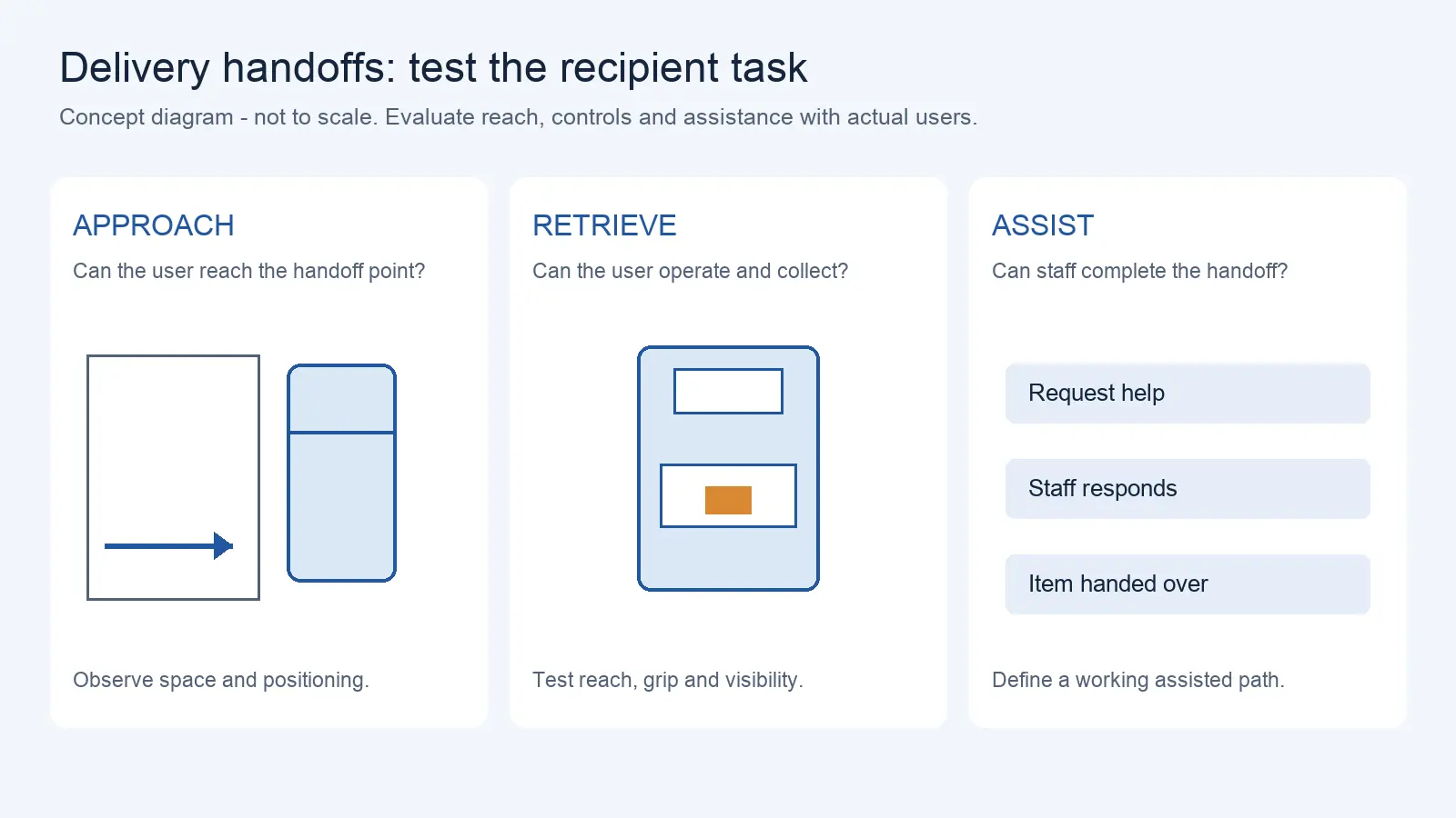
Delivery Robot Accessibility: Tray Reach, Controls, and Assisted Handoffs
Oct 12, 2026
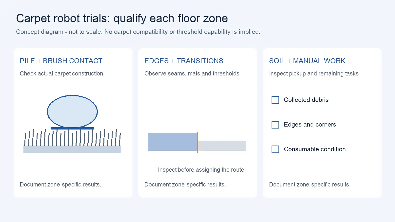
Commercial Carpet-Vacuuming Robots: Pile, Edge Transitions, and Maintenance Limits
Oct 12, 2026
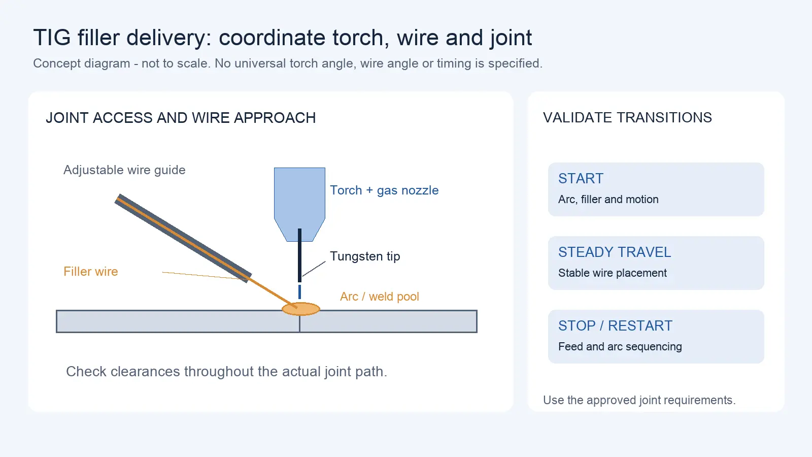
Robotic TIG Filler-Wire Delivery: Feed Angle, Arc Access, and Stop-Start Quality
Oct 12, 2026
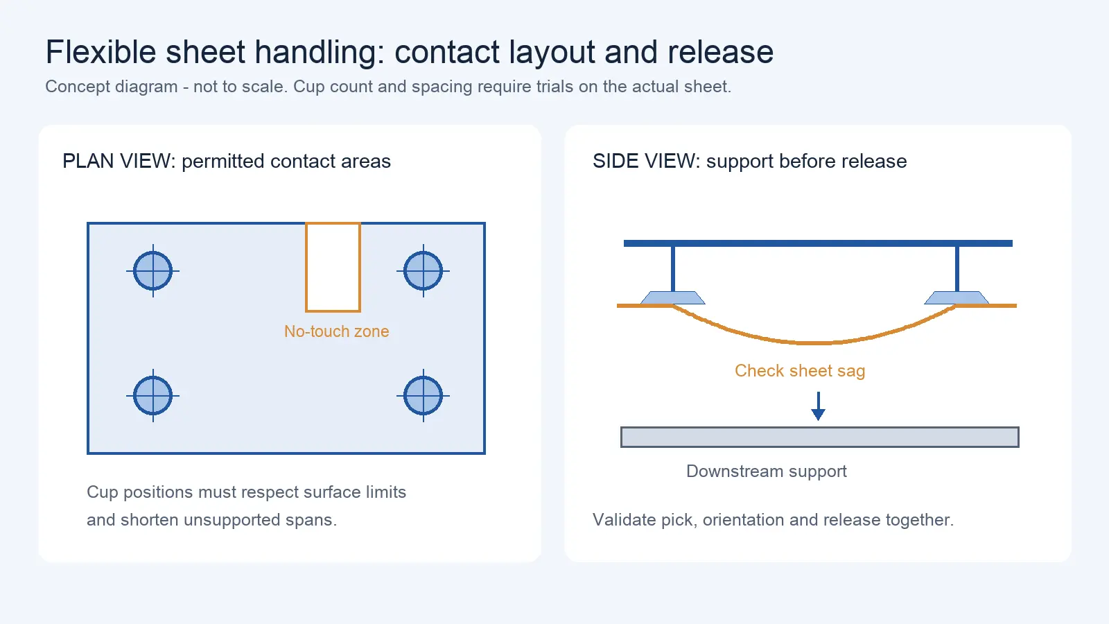
Suction Cup Layout for Flexible Sheets: Sag, Local Stress, and Controlled Release
Oct 12, 2026
When a mobile robot datasheet states “8 hours runtime” or “2,000 cycle life,” those numbers are only meaningful if you know the conditions under which they were measured. A robot running empty on a flat floor at low speed will run far longer than the same robot carrying its maximum payload up a ramp. A battery’s cycle life rating depends on depth of discharge, temperature, charge rate, and end-of-life threshold — without these conditions specified, the number is not actionable. This article explains how to read mobile robot battery specifications, which numbers are useful for comparison, which require context, and what to ask a supplier before relying on their runtime or cycle life claims.
Ah Is Not Enough: Compare Energy in Wh
Battery capacity is often stated in ampere-hours (Ah). This is useful for quick reference, but it can be misleading when comparing batteries with different voltages. A 24V 20Ah battery and a 48V 10Ah battery both say “20Ah” and “10Ah” respectively, but they store very different amounts of energy.
The correct unit for comparing energy capacity is watt-hours (Wh), calculated as:
Wh = Nominal Voltage (V) × Capacity (Ah)
Using this formula:
- 24V × 20Ah = 480 Wh
- 48V × 10Ah = 480 Wh
These two batteries store the same amount of energy despite having different Ah ratings. If you compare only by Ah, you might assume the 24V battery has twice the capacity — when in fact they are equivalent.
| Parameter | What It Tells You | Limitation |
| Ah (ampere-hours) | Charge capacity at a given voltage | Not comparable across different voltage systems |
| Wh (watt-hours) | Total energy stored | Directly comparable across systems; the correct unit for battery comparison |
| Nominal voltage | System voltage class | Determines motor/controller compatibility; affects charging infrastructure requirements |
When evaluating AMR battery specifications, always convert Ah to Wh before comparing devices. If a supplier only provides Ah without voltage, request the nominal voltage so you can calculate Wh yourself.
Rated Runtime vs Usable Runtime
Datasheet runtime figures are typically measured under controlled conditions: a specific payload (often empty or a standard test weight), a specific speed, a flat surface, no inclines, no obstacles, and a moderate ambient temperature. These conditions rarely match real warehouse or factory environments.
Several factors reduce usable runtime below the rated figure:
Payload. Every additional kilogram the robot carries increases motor current draw. A robot running at its maximum rated payload will see runtime reduced compared to an empty run — the magnitude depends on the drive system efficiency and the proportion of energy spent on acceleration versus steady-state motion. Request runtime data at your expected payload, not just at the test weight.
Speed and acceleration profile. Higher speeds and aggressive acceleration consume more energy per meter traveled. A robot running at its maximum speed continuously will deplete its battery faster than one running at 60% speed with smooth acceleration profiles. Stop-and-go operation in narrow aisles is particularly energy-intensive because each acceleration event draws peak current.
Traffic and obstacle density. In a busy warehouse with pedestrians, forklifts, and other robots, the AMR frequently slows, stops, and reroutes. Each of these events consumes energy that a straight-line test run does not account for. Dynamic path planning and obstacle avoidance are not free — they cost processing power and motor energy.
Temperature. Battery performance changes with temperature. LFP batteries have specified operating temperature ranges that vary by manufacturer and cell design, but at low temperatures, internal resistance increases and usable capacity decreases. At high temperatures, self-discharge accelerates. A robot operating in a cold storage warehouse will have shorter runtime than the same robot in a climate-controlled environment, even with the same battery. Verify the operating temperature range with the specific battery manufacturer.
Auxiliary loads. The battery powers more than the drive motors. Top modules (conveyors, lifts, scanners), communication modules (Wi-Fi, 5G), safety sensors (LiDAR, bumper strips), and on-board computers all draw power. A robot with an active top-module conveyor and a high-power vision system will have shorter runtime than the same chassis without those loads. Request the power draw of all auxiliary equipment and factor it into your runtime calculation.
How Payload, Speed, Traffic and Temperature Change Runtime
Consider an illustrative scenario to show how these factors compound:
Illustrative scenario: A mobile robot is rated for 8 hours runtime. The rating was measured at 50% payload, 1.2 m/s, flat floor, 22°C, no obstacles, no top module. In actual deployment, the robot carries 80% payload, averages 0.8 m/s due to traffic, operates in a warehouse at 15°C, and powers a top-module lift and scanner. The combined effect of these deviations will reduce actual runtime below the rated figure — potentially significantly. The exact reduction depends on the specific robot, duty cycle, and environment. This estimate assumes roughly additive reductions from each factor — payload draw increase, temperature derating, auxiliary load, and traffic-induced stop-and-go — rather than a single measured test result.
This is not a defect in the robot. It is the difference between a laboratory rating and a real duty cycle. The problem arises when buyers plan staffing and shift schedules based on the rated runtime without accounting for these reductions.
Charge Time, Opportunity Charging and Battery Swap
Charging strategy affects robot availability as much as battery capacity. Three approaches are common in AMR deployments:
Full charge cycles. The robot operates until the battery reaches a low threshold, then returns to a charging station for a full charge. Charge time depends on battery capacity and charger power. Request the supplier’s stated charge time at the specified charger power and battery configuration. Fast charging increases heat generation and may reduce cycle life if not managed by the BMS.
Opportunity charging. The robot charges during brief idle periods — between tasks, during loading/unloading stops, or at designated top-up stations. This approach keeps the battery in a moderate SOC range and avoids deep discharge cycles. The optimal SOC range depends on the battery chemistry and BMS design — some manufacturers specify a preferred range, others do not. Opportunity charging can extend daily operating time significantly, but it requires charging stations at multiple locations and a fleet management system that routes robots to charge when idle. The trade-off: more infrastructure cost, but higher robot utilization.
Battery swap. A depleted battery is physically replaced with a charged one, allowing the robot to return to operation in minutes. This approach is common in AGV deployments with high-utilization requirements. The trade-off: requires spare batteries, swap infrastructure (manual or automated), and batteries must be designed for swap-friendly access. Not all AMRs support battery swap — verify this as an RFQ item if your operation requires near-continuous uptime.
| Charging Strategy | Best For | Infrastructure Required | Trade-off |
| Full charge | Single-shift operations with predictable downtime | One charging station per robot | Robot unavailable during charge (duration depends on battery capacity and charger power) |
| Opportunity charging | Multi-shift operations with variable task flow | Multiple charging stations across the facility | Higher infrastructure cost; requires fleet management integration |
| Battery swap | 24/7 operations with no tolerance for charging downtime | Spare batteries, swap mechanism (manual or automated) | Higher battery inventory cost; not all AMRs support swap |
Cycle Life, Chemistry and Replacement Planning
Cycle life — the number of charge-discharge cycles a battery can deliver before its capacity degrades to a specified threshold (typically 80% of original capacity) — is one of the most commonly misunderstood battery specifications.
The DoD problem. Cycle life is always specified at a particular depth of discharge (DoD). A battery rated for 2,000 cycles at 80% DoD may deliver more cycles at a lower DoD, or fewer cycles at 100% DoD. The relationship between DoD and cycle life is non-linear and varies by cell chemistry, design, and manufacturer. If a supplier states “3,000 cycle life” without specifying DoD, the number is not actionable. Always request cycle life data at a specific DoD level relevant to your operation.
Chemistry matters. Lithium iron phosphate (LiFePO4, or LFP) is the dominant chemistry for AMR and AGV batteries due to its safety characteristics and cycle life. LFP batteries are thermally stable — the cathode material does not release oxygen under thermal stress, meaning the battery does not sustain combustion in the way that lithium cobalt oxide (LCO) or some nickel manganese cobalt (NMC) chemistries can. LFP cathodes decompose at significantly higher temperatures than LCO or LMO cathodes (ScienceDirect, LFP overview). This is not a theoretical concern: a study on LFP batteries for unmanned tunnel inspection robots noted that “the most serious risk associated with these robots is the potential for failures to spread to industrial facilities due to fires in the battery and power system” (IEEE, 2024; S-tier academic source).
The trade-off is energy density: LFP batteries have lower energy density than some other lithium chemistries (ScienceDirect, LFP overview). For a mobile robot where battery weight affects payload capacity, this means a larger or heavier battery pack for the same runtime compared to higher energy-density alternatives.
Lab data vs marketing claims. Academic literature and commercial claims for LFP cycle life vary widely depending on test conditions — DoD, temperature, charge/discharge rate, and end-of-life threshold all affect the result. Commercial claims of very high cycle counts may reflect different test conditions (lower DoD, lower discharge rate, controlled temperature) or optimistic projections based on accelerated testing. When planning battery replacement timelines, request the supplier’s test methodology and compare against independent data, not just the headline number.
| Parameter | LFP (LiFePO4) | NMC | LCO |
| Energy density | Lower than NMC/LCO | Higher than LFP | Highest (consumer electronics) |
| Cycle life at 80% DoD | Varies by manufacturer and test conditions; request supplier data | Varies; typically lower than LFP | Lowest |
| Thermal stability | Higher than LCO/NMC; does not sustain combustion the way some other lithium chemistries can | Moderate; requires robust BMS | Poor; thermal runaway risk |
| Suitability for AMR | Preferred — safety and cycle life advantages | Used when higher energy density needed | Not suitable for industrial robots |
| Operating temperature | Varies by manufacturer and cell design | Varies by manufacturer | Narrower range |
Charging Stations and Electrical Infrastructure
Battery specifications do not exist in isolation — they determine what your facility must provide:
Charging station placement. Opportunity charging requires stations at multiple points along the robot’s typical route. The stations need dedicated power circuits, clear floor space, and network connectivity for fleet management integration. Placement is not just about convenience: if the robot must travel 60 meters to reach a charger, that travel time and energy cost reduce the benefit of opportunity charging.
Electrical capacity. Each charger draws power from the facility’s electrical system. A fleet of robots with simultaneous fast charging requires dedicated capacity that may exceed available circuits in older facilities. Request the charger’s power draw specification and verify available capacity with your facilities team before specifying charger requirements.
Charging vs discharging temperature. LFP batteries have different temperature ranges for charging and discharging. Charging at low temperatures can cause lithium plating, which permanently damages the battery. If your facility operates in cold conditions, confirm that the BMS includes temperature-based charge inhibition — preventing charge attempts when the battery is below the safe charging temperature threshold.
What Battery Data to Request from a Supplier
When evaluating AMR battery specifications for procurement, request the following data in writing:
Capacity and energy:
- Nominal voltage (V)
- Capacity in Ah and calculated Wh
- Usable energy in Wh (after BMS reserves and low-voltage cutoff)
- Chemistry type (LFP, NMC, or other)
Runtime characterization:
- Test conditions for stated runtime: payload, speed, surface, temperature, auxiliary loads
- Runtime at 100% payload vs 50% payload (if available)
- Runtime at typical operating temperature range, not just ideal conditions
Charging:
- Full charge time at standard charger power
- Full charge time at fast charger power (if supported)
- Whether opportunity charging is supported and at what SOC range
- Whether battery swap is supported
Cycle life:
- Cycle life at specified DoD (80% is standard reference)
- End-of-life definition (typically 80% of original capacity)
- Test methodology: temperature, charge/discharge rate, cycling protocol
BMS and safety:
- BMS functions: overcharge protection, over-discharge protection, short circuit protection, temperature protection, cell balancing
- Communication interfaces (SMBus, I2C, RS485, CAN bus, or other)
- Safety certifications: IEC 62133 (battery safety), IEC 62619 (industrial battery safety), UN38.3 (transport safety), UL 1642 (cell safety, US market)
- Note: UN38.3 is a transport regulation, not a performance standard. It verifies the battery is safe for shipping — it does not certify operational performance or cycle life.
Replacement and service:
- Expected battery replacement interval based on your duty cycle
- Battery availability for replacement (lead time, spare part pricing)
- Whether the battery is user-replaceable or requires technician service
A Duty-Cycle Calculation Worksheet
Use this worksheet to estimate whether a robot’s battery specification will meet your operational requirements. The goal is not to predict exact runtime — too many variables are site-specific — but to identify whether the rated capacity provides enough margin for your worst-case shift.
| Parameter | Your Value | Supplier’s Rated Value | Margin |
| Shift length (hours) | |||
| Average payload (% of max) | |||
| Average speed (m/s) | |||
| Operating temperature (°C) | |||
| Number of stops/obstacles per hour | |||
| Auxiliary loads (top module, sensors) | |||
| Rated runtime (hours) | |||
| Estimated actual runtime (hours) | |||
| Estimated actual runtime / Shift length | ≥1.2 recommended | ||
| Charge time (hours) | |||
| Charging strategy (full/opportunity/swap) | |||
| Cycle life at your DoD | |||
| Estimated battery replacement interval (years) |
Request a Quote or Technical Evaluation
Tell us what you need the robot to do. Even if some technical details are not yet confirmed, our team can help evaluate suitable options.
Please share, if available: application, key requirements, site and integration conditions, quantity, destination, and target timeline.
Send Your RequirementsRule of thumb: If estimated actual runtime divided by shift length is below 1.2, the battery specification is marginal for your operation. Either increase battery capacity, add opportunity charging stations, or reduce the robot’s average load. A margin below 1.0 means the robot will run out of power before the shift ends.
Share on Social:


Contact Us
In This Article
Delivery Robot Accessibility: Tray Reach, Controls, and Assisted Handoffs
Oct 12, 2026
Commercial Carpet-Vacuuming Robots: Pile, Edge Transitions, and Maintenance Limits
Oct 12, 2026
Robotic TIG Filler-Wire Delivery: Feed Angle, Arc Access, and Stop-Start Quality
Oct 12, 2026
Suction Cup Layout for Flexible Sheets: Sag, Local Stress, and Controlled Release
Oct 12, 2026