

 Contact Us

 Home /
 Mobile Robot Charging Infrastructure Planning: Charger Count, Electrical Capacity, Placement, and Redundancy
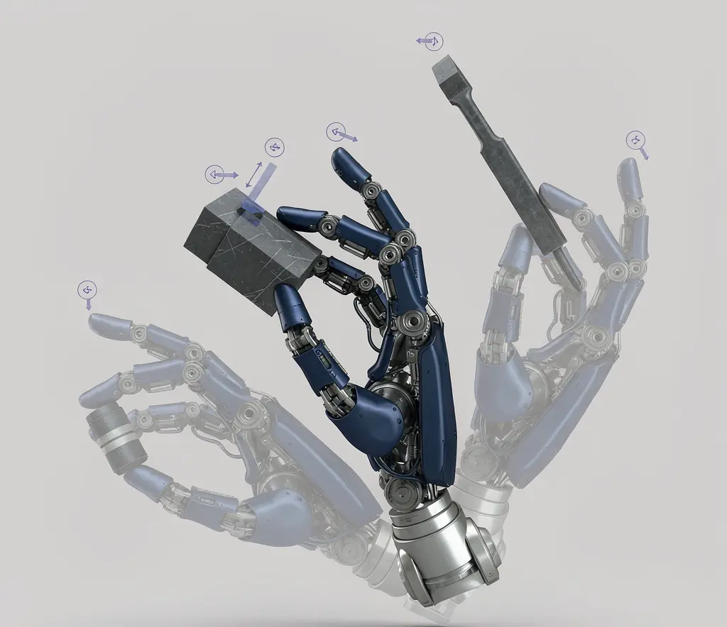
Humanoid Robot Hand Dexterity Verification: Grasp Set, Tool Use, Force Control, and Recovery
Oct 08, 2026

Industrial Exoskeleton Fit and Sizing: Anthropometry, Adjustment Time, PPE, and Shared-Device Programs
Oct 08, 2026

Robot Duty Cycle and Thermal Limits: Why Rated Payload and Speed Do Not Guarantee Continuous Operation
Oct 08, 2026

Robot IP Ratings Explained: What IP54, IP65, and IP67 Do — and Do Not — Prove
Oct 08, 2026
A fleet can have enough chargers in total and still face queues when charging windows overlap or docks are in the wrong locations. Plan charging capacity around the duty cycle, site layout, equipment compatibility and agreed electrical limits.
Charging queues can reflect overlapping demand, charger placement, equipment compatibility or faults. Check those causes against the fleet's duty cycle before changing the charger count.
This article covers what to plan for, what standards apply, and what to verify with your supplier before installing charging infrastructure.
Start With the Duty Cycle, Not the Catalog
Charging infrastructure planning should begin with the fleet's operational profile:
- Run window: How many hours per day does each robot actively run missions?
- Charge window: When can robots charge, and for how long? Is it opportunity charging (short top-ups between tasks) or shift charging (extended charging during downtime)?
- Target state of charge (SOC): What minimum SOC does a robot need to start a mission? What SOC triggers a return to the charger?
Battery capacity and charge behavior are inputs to infrastructure planning. For battery-spec comparison, see mobile robot battery specifications.
- Task peaks: Mission peaks and charging demand can overlap. Use mission logs and SOC profiles to identify when robots require charging and test the effect of dispatch and charging policies.
The critical insight: fleet size does not equal charger count. You may need fewer chargers than robots if duty cycles allow staggered charging, or you may need chargers in specific locations to avoid traffic bottlenecks even if the total count is lower than the fleet size.
Charger Count: A Framework, Not a Formula
There is no universal formula for charger count because the answer depends on:
- Battery capacity and discharge rate per robot
- Charging rate (how fast the charger replenishes the battery)
- Duty cycle (ratio of active time to total available time)
- Charging policy (opportunity charging vs. shift charging)
- Fleet size and task distribution
- Simultaneous charging peak (how many robots may charge at the same time during worst-case scenarios)
Instead of a formula, use a planning approach:
- Map the worst-case scenario: all robots return to charge at the same time (typically at shift change or during a task gap).
- Calculate the peak power demand: number of simultaneously charging robots times charger input power.
- Determine whether staggered charging is feasible: can the fleet management system schedule charging to smooth the peak?
- Estimate required charger-hours from the operating profile and charging curves, then test whether the available charging windows and dock capacity can meet peak demand and failure scenarios.
- Add redundancy: if one charger fails, can the fleet continue operating with the remaining chargers?
Do not accept a supplier's “one charger per robot” recommendation without understanding the reasoning behind it. It may be a safe default, but it may also be over-provisioned or under-provisioned for your specific operation.
Electrical Capacity: Beyond the Charger Spec
Each charger draws power from your facility's electrical system. The total demand depends on:
- Voltage and frequency: Different countries have different standards (208V/60Hz, 400V/50Hz, etc.). Chargers must match the local supply.
- Power per charger: The rated input power of each charger, typically specified on the datasheet.
- Peak current: When multiple chargers start simultaneously, the inrush current can exceed the steady-state current significantly.
- Circuit protection: Each charger circuit needs appropriate breakers and protection.
- Grounding: Proper grounding is essential for safety and equipment protection.
- Short-circuit protection: The electrical installation must handle fault conditions.
The key point: your facility's electrical capacity must handle the worst-case simultaneous charging load, not just the average. For illustration, ten chargers drawing 3 kW each would represent 30 kW of aggregate input demand if they operated simultaneously. This is not a branch-circuit design. A qualified electrical designer should assess circuit allocation, voltage, phase loading, rated input current, inrush characteristics, protective devices and any validated load-management scheme under the applicable local requirements.
IEC 60364 is the international standard series for low-voltage electrical installations. Several parts are relevant:
- IEC 60364-1:2025 covers basic principles, general characteristics assessment, and definitions.
- IEC 60364-4-41 covers protection against electric shock.
- IEC 60364-4-43 covers overcurrent protection.
- IEC 60364-4-44:2024 covers protection against voltage disturbances and electromagnetic disturbances.
- IEC 60364-5-52 covers the selection and erection of wiring systems.
IEC 60364 provides the framework, but the actual installation must comply with local electrical codes. A separate standard, IEC 60364-7-717, addresses particular requirements for mobile or transportable units; its applicability to fixed warehouse charging positions needs to be assessed separately and should not be assumed simply because the product is called a mobile robot. Your electrical engineer or contractor should confirm which parts and editions apply and that the planned installation meets local requirements.
Charger Placement: Traffic, Access, and Safety
Where you put chargers affects traffic flow, safety, and operational efficiency. Charging placement is a fleet-layout decision tied to traffic, throughput and expansion; see AMR fleet design for large warehouses.
- Dock location: Chargers should be placed where robots naturally transition between tasks, not in high-traffic aisles where they create bottlenecks.
- Queue space: Robots waiting to charge need a queue area. If the queue extends into a traffic lane, it blocks other robots and forklifts.
- Fire and emergency access: Chargers must not block fire exits, emergency routes, or fire suppression equipment.
- Maintenance access: Chargers themselves need maintenance. Leave space for inspection, cable management, and replacement.
- Network coverage: If chargers communicate with the fleet management system, they need reliable network coverage at their location.
- Environmental conditions: Chargers have temperature limits. Do not install them in areas that exceed the specified operating range.
Dock Compatibility and Robot Assignment
Not all chargers work with all robots. Compatibility factors include:
- Dedicated vs. shared chargers: Can one charger serve multiple robot models, or is it model-specific?
- Automatic docking tolerance: How precisely must the robot align with the charging contacts? Navigation spec (how accurately the robot reaches a target zone) is not the same as docking accuracy (how precisely it aligns with the physical interface).
- Communication requirements: Does the charger need to communicate with the robot or the fleet manager? If so, what protocol and what happens when communication fails?
Do not assume that chargers from one supplier are compatible with robots from another, or that different models from the same supplier share chargers. Verify compatibility for each specific combination.
Redundancy and Failure Scenarios
What happens when a charger fails? Without redundancy, a single charger failure can reduce fleet capacity or create a charging bottleneck. For broader robot, dock, network and software failure planning, see robot fleet business continuity. Plan for:
- Single point of failure analysis: If charger X fails, how many robots are affected? Can they reroute to other chargers?
- Spare dock availability: Determine spare docking capacity based on downtime tolerance, repair time, charger compatibility and failure scenarios rather than a fixed number.
- Degraded operation: Can the fleet operate at reduced capacity while a charger is repaired? What is the impact on throughput?
What to Verify With Your Supplier
Charger specifications. What is the rated input and output (voltage, current, power)? Is the charger model-specific or compatible with multiple robot models?
Maximum simultaneous charging. How many robots can charge simultaneously on a single circuit? What is the peak power demand?
Communication requirements. Does the charger communicate with the fleet manager? What protocol? What happens when communication fails?
Installation spacing. What are the minimum clearances around the charger for safety, ventilation, and maintenance?
Environmental limits. What temperature range does the charger support? Are there ventilation or fire suppression requirements?
Automatic docking tolerance. What is the lateral and angular tolerance for automatic docking? How does this compare to the robot's navigation accuracy?
Failure behavior. What happens when a charger fails? Does the robot detect the failure and reroute, or does it sit at the dead charger?
Common Pitfalls
Guessing charger count. Without a duty cycle analysis, any charger count is a guess. It may be too many (wasted capital) or too few (charging bottlenecks).
Planning for average load, not peak. The electrical system should handle the worst-case simultaneous charging load. Planning only for average load risks breaker trips, voltage drops or inadequate protection. A qualified designer can consider validated load-management schemes, but do not substitute unverified dispatch assumptions for proper electrical design.
Ignoring traffic impact. A charger placed in a high-traffic area creates bottlenecks that reduce fleet efficiency more than the charger improves it.
Assuming cross-model compatibility. Chargers are often model-specific. Do not assume that a charger for one robot works with another without verifying.
Confusing navigation accuracy with docking accuracy. Navigation accuracy and docking accuracy are different measurements. Verify each against the actual model and interface conditions rather than assuming a single number applies.
What to Ask Your Supplier
- How many chargers do we need for our fleet size and duty cycle, and how was that number calculated?
- What is the peak power demand if all robots charge simultaneously?
- Is the charger compatible with multiple robot models, or is it model-specific?
- What is the automatic docking tolerance, and how does it compare to the robot's navigation accuracy?
- What are the environmental limits for charger installation (temperature, ventilation, fire suppression)?
- What happens when a charger fails: does the robot reroute automatically?
- What communication protocol does the charger use, and what happens when it loses connection?
- What are the minimum installation clearances for safety and maintenance?
Planning chargers for a new AMR or mobile-robot fleet? Share the fleet size, duty cycle, charger specifications, facility voltage/frequency, proposed dock locations and any fleet-control constraints. AIsirRobot can help organize the interface and infrastructure questions and coordinate the required technical information with the relevant manufacturer or integrator. Final electrical design, protection, installation and commissioning must be completed by qualified parties under the applicable local requirements.
Share on Social:


Contact Us
In This Article
Humanoid Robot Hand Dexterity Verification: Grasp Set, Tool Use, Force Control, and Recovery
Oct 08, 2026
Industrial Exoskeleton Fit and Sizing: Anthropometry, Adjustment Time, PPE, and Shared-Device Programs
Oct 08, 2026
Robot Duty Cycle and Thermal Limits: Why Rated Payload and Speed Do Not Guarantee Continuous Operation
Oct 08, 2026
Robot IP Ratings Explained: What IP54, IP65, and IP67 Do — and Do Not — Prove
Oct 08, 2026