

 Contact Us


 Home /
Robotic Welding Torch Servicing: Nozzle Cleaning, Wire Cutting, and TCP Drift
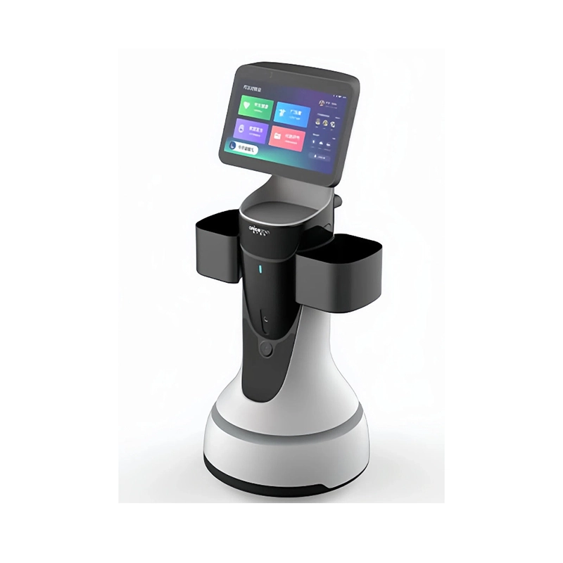
Multilingual Guide Robots: Translation Quality, Place Names, and Content Ownership
Oct 15, 2026
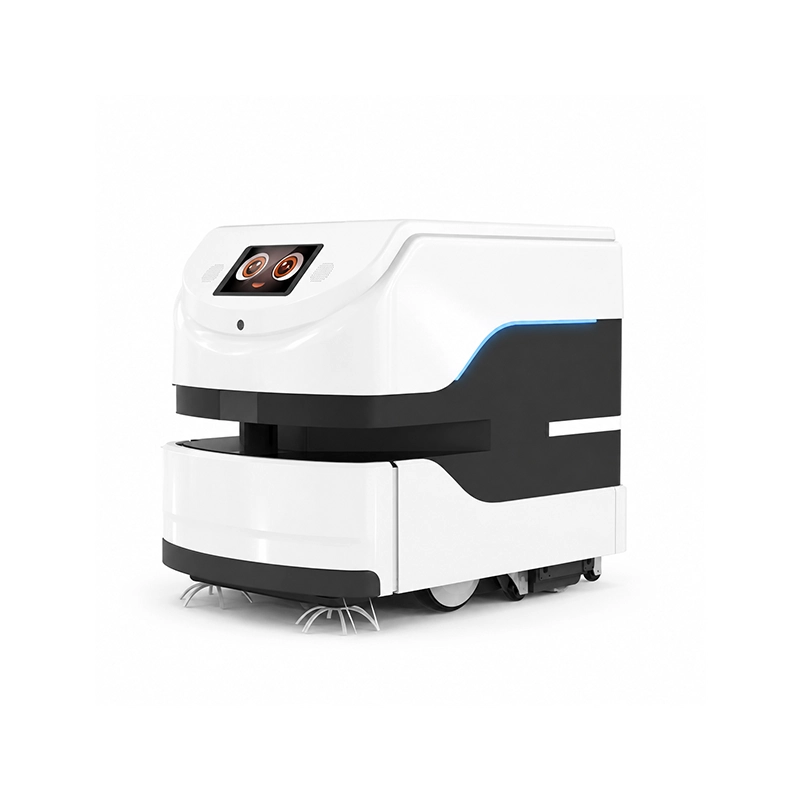
Proving Cleaning Quality Beyond Coverage Maps: Soil Removal, Inspection, and Rework
Oct 15, 2026
Robot Conveyor Tracking: Encoders, Trigger Timing, and Moving Coordinate Frames
Oct 15, 2026
Magnetic Grippers for Thin Steel Sheets: Air Gaps, Double-Sheet Pickup, and Release
Oct 15, 2026
A welding robot scheduled for twenty hours a day will deliver less arc-on time once torch-related stops are counted. It stops for spatter to be knocked off the nozzle, for the wire to be cut to the required condition, for the torch to be checked after a collision, and for the tool center point to be confirmed before the next pass. Repeated service stops can consume productive time, especially when each one requires an operator to intervene. Measure their actual contribution before sizing the station. Servicing the torch well is the difference between a robot that welds and a robot that waits.
This article is for the people who specify and maintain the auxiliary station that does that work. It maps the torch-related stops, compares the required service functions, places the service station inside the real cell, accounts for the tool geometry change after servicing, chooses evidence-based service triggers, and validates availability and recovery. The thread running through it is that torch servicing is a subsystem with its own configuration, and treating it as an accessory is how cells end up with avoidable downtime.
Map Torch-Related Stops and Defects
Start by knowing why the cell stops. The reasons cluster around a few wear and contamination mechanisms.
Nozzle blockage: spatter builds up inside the gas nozzle, restricting shielding-gas flow and distorting the gas shield. A partially blocked nozzle can produce porosity that only shows up later, which makes it worse than a clean stop.
Contact-tip wear: the contact tip guides the wire and conducts current, and it wears as the wire runs through it. A worn tip gives inconsistent electrical contact, which shows up as arc instability and inconsistent penetration.
Wire feed problems: the wire can bird-nest at the feed rolls, kink, or take a poor set. Wire condition interacts with the liner, the drive rolls, and the torch angle.
Torch angle and position: a collision or a program error can displace the torch, changing both the angle and the tool center point.
Each of these produces a different symptom, and each needs a different response. Mapping them for the specific cell, with the observed frequency, is what turns torch servicing from a habit into a plan. Note that wire-feed mechanisms and wire handling are treated elsewhere; this article's scope is the torch service subsystem and the recovery of the tool state, not the design of the wire feeder.
Compare Required Service Functions
Not every cell needs every service function, and assuming they all come as a set is a common purchasing error.
Nozzle cleaning: removing spatter from the surfaces reached by the selected method. For example, ABICOR BINZEL's BRS-CC operating instructions, dated 25 October 2021, describe robot-output control, clamping on the gas nozzle and a reamer matched to the nozzle and torch geometry. Specify the actual cleaning surfaces and matching parts instead of assuming that every station cleans the entire torch.
Wire cutting: trimming to the process-defined stick-out and required end condition. Verify cut position, bent-wire behavior and arc-start repeatability on the actual wire; do not prescribe a square end as a universal requirement.
Torch checking and calibration: measuring or confirming the torch position and, where the function exists, providing a tool center point measurement reference.
Replacement: changing consumables such as the nozzle, tip, or liner, which is a different function from cleaning them.
ABB's Torch Service Center 2013 data sheet, Rev A, July 2019 describes a modular system with nozzle cleaning, wire cutting, TCP gauging and calibration, and release-agent injection. Its stated control-system scope is IRC5 with the specified RobotWare generation. This is evidence for that documented configuration, not proof that every cleaner measures TCP or that an offered station fits a different controller. Confirm the supplied modules and software compatibility separately.
Each function adds hardware, time, and failure modes. The buyer should decide, per cell, which are required by the process and which are not, rather than buying a fully loaded station that spends most of its capability unused. The right question is which functions reduce the specific stops identified in the previous step.
Place the Service Station in the Real Cell
A torch service station is a mechanical object that has to live somewhere in a cell that is already crowded.
Reachability: can the robot's torch actually reach the station, on the path the program will use, without an awkward wrist configuration? A station that is geometrically reachable but requires the robot to twist into a near-singularity will cause problems in production.
Fixture interference: does the station conflict with the welding fixture, the part, or the robot's own envelope when the robot is at its service position? The service position is a real robot posture, and it has to coexist with everything else.
Waste collection: the station produces waste, whether it is knocked-off spatter, trimmed wire, or anti-spatter fluid overspray. Where does it go? A station that deposits debris into the weld area is trading one defect source for another. A Chinese mainland manufacturer example, Beijing Wusee's WHC-R52C, describes routing cleaning debris and excess anti-spatter fluid into a collection box, with cut wire directed to a designated location through a corrugated tube. Use that as a layout question: locate each discharge point, collection container and access route on the offered cell drawing. It is a product-specific design description, not a measured comparison of station performance.
Maintenance space: can a person reach the station to service it, and does servicing the station stop the cell? The station itself has consumables and wear parts, and its own maintenance has to be possible without dismantling the cell. Separate programmed torch-service motion from human work on the station; the latter needs the equipment's documented isolation and controlled-restart procedure.
These are layout decisions, and they belong in the cell design, not in a retrofit after the cell is built. A station squeezed in at the end is a station that will be reached awkwardly and serviced reluctantly.
Account for Tool Geometry Changes
Servicing can change the effective tool geometry. Verify the reference when the work affects the torch, wire position or stick-out.
After a collision, neck replacement or any consumable change that affects wire position, stick-out or torch geometry, verify the effective tool center point against the approved reference. Replacing a liner alone does not prove that the TCP has moved. If the robot's program assumes the old geometry, the arc start and the weld path will be off. This is why a service function that includes a tool center point measurement or calibration reference is valuable: it lets the cell re-establish the correct tool frame after a change.
Use the robot and torch manufacturers' procedures to define the reference, method and acceptance limits in the cell's calibration plan. Choose a station that supports that process, and connect torch changes to the required geometry checks. A cleaning cycle, a wire cut and a TCP verification are distinct events; record which one was completed before releasing the next weld.
Choose Evidence-Based Service Triggers
Set the service trigger for the actual process. A documented OEM interval for a defined configuration is a useful starting point; it is not automatically the right interval for every welding cell.
There are three legitimate inputs to the trigger. The first is the manufacturer's recommended interval, which is a starting point based on expected conditions. The second is actual measured wear: how much spatter has accumulated, how worn the tip is, how the arc behaves. The third is the quality record: when defects appear, what was the torch's condition at the time.
The right trigger combines them. A cell that runs a heavily spattering process may need more frequent cleaning than the manual says. A cleaner-running cell should review permissible trigger changes with the OEM and process owner while retaining required scheduled checks. The trigger should be set from the observed data for that cell, and it should be reviewed as conditions change. A fixed daily interval chosen without data will either over-service or under-service, and both cost money.
For each trigger review, record process, wire, shielding gas, parameter range, torch condition and the reason for any change. Keep anti-spatter fluid and other consumables within the manufacturer's stated compatibility conditions.
Validate Availability and Recovery
The last step is to measure the subsystem the way it will be experienced: as a source of both service and downtime.
Record the time each service action actually takes, from the robot leaving the weld to returning to it. This is the true cost of the service function, and it is usually longer than the nominal cleaning time once travel and positioning are included. Sum it across a shift and compare it to the welding time; that ratio is what the station is trading against.
Then record the failures. What happens when the station's function fails, when the wire is not cut cleanly, when the cleaning is incomplete, when the station jams? Each failure needs a defined response and a responsible party. The BRS-CC manual distinguishes missing cutting action, inadequate cutting capacity and a bent free wire end, with different checks for supply, actuation, cutting-edge condition and torch approach. Build the fault list from the installed model's instructions; these are diagnostic categories, not a substitute for a qualified maintenance procedure. Some will be recoverable by the robot, some by an operator, and some only by maintenance. Scheduled service time, unplanned stops and recovery duration all belong in the cell-availability calculation; the plan should state who owns each recovery.
The result is a torch service subsystem that is specified like the rest of the cell: with its functions chosen for a reason, its station placed for reachability and maintainability, its tool-geometry change tied to calibration, its triggers set from data, and its failures assigned. That is what keeps the robot welding instead of waiting.
Use Real Stops to Scope the Torch-Service Station
Send the welding process, torch model, existing cell layout, typical stoppages and the service functions under consideration. AIsirRobot can help compare suitable station configurations and identify the manufacturer information needed for placement, compatibility and service timing. Final TCP verification and integration remain with the qualified cell team. Assess the torch-service application.
Share on Social:


Contact Us
In This Article
Multilingual Guide Robots: Translation Quality, Place Names, and Content Ownership
Oct 15, 2026
Proving Cleaning Quality Beyond Coverage Maps: Soil Removal, Inspection, and Rework
Oct 15, 2026
Robot Conveyor Tracking: Encoders, Trigger Timing, and Moving Coordinate Frames
Oct 15, 2026
Magnetic Grippers for Thin Steel Sheets: Air Gaps, Double-Sheet Pickup, and Release
Oct 15, 2026