

 Contact Us

 Home /
 Robot Press-Fit and Insertion Automation: Force-Displacement Curves, Compliance, Alignment, and Jam Detection

Reusable Pallets for Autonomous Handling: Repair, Replace, or Standardize the Carrier Fleet?
Oct 10, 2026
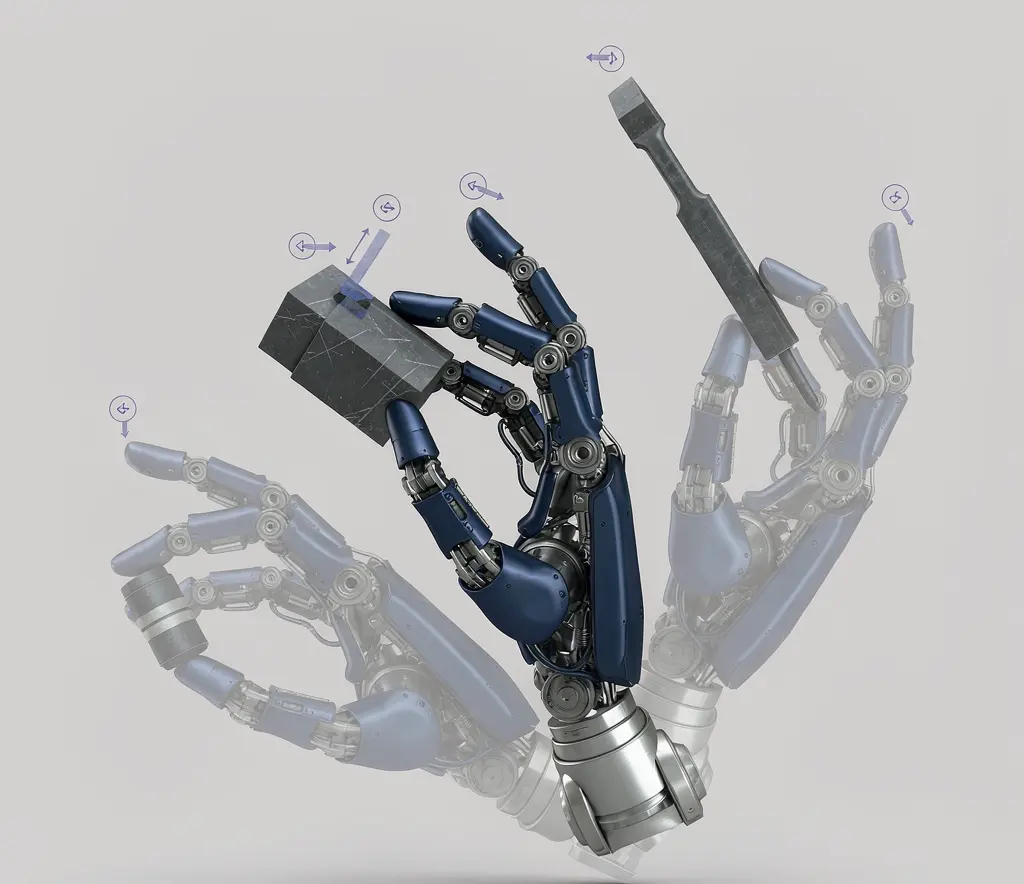
Humanoid Robot Hand Dexterity Verification: Grasp Set, Tool Use, Force Control, and Recovery
Oct 08, 2026

Industrial Exoskeleton Fit and Sizing: Anthropometry, Adjustment Time, PPE, and Shared-Device Programs
Oct 08, 2026

Robot Duty Cycle and Thermal Limits: Why Rated Payload and Speed Do Not Guarantee Continuous Operation
Oct 08, 2026
The following scenario is illustrative and does not represent data from any specific deployment. A robot presses a bearing into a housing. The robot's position repeatability is 0.02 mm. The bearing jams halfway in, the robot continues pushing, and the housing cracks. The robot's position was correct, but the parts were not aligned. The bearing had a slight lead-in chamfer, but the housing bore had a burr on one side that the robot could not compensate for. A human operator would have felt the resistance, wiggled the bearing, and either seated it or stopped. The robot, following a position-based command, pushed until something broke. This article covers how to automate press-fit and insertion operations using force-displacement evidence, mechanical compliance, and jam detection to prevent damage and verify assembly success.
Why Robot Position Repeatability Is Not Assembly Success
Robot position repeatability measures how precisely the robot returns to a commanded position. It does not measure whether the parts are aligned when the robot arrives at that position. In an insertion or press-fit operation, the actual position of the hole or receiver depends on:
- Part tolerance: The hole may be at a different position than nominal
- Fixture tolerance: The fixture may hold the part in a slightly different position each time
- Part deformation: Clamping or thermal expansion may shift the hole
- Robot deflection: Under load, the robot may deflect from its commanded position
- Tool offset: The EOAT may not hold the part at the exact expected position
The cumulative effect of these variations can be several times the robot's repeatability specification. A robot with 0.02 mm repeatability may still fail to insert a part if the hole is 0.1 mm off position. Position accuracy alone does not guarantee assembly success. The assembly process must accommodate the actual variation, not assume that the robot's repeatability eliminates it.
Robot repeatability versus accuracy defines the position metrics that do not directly prove successful insertion.
Map the Tolerance Stack and Reaction Path
Before selecting a compliance or force control strategy, the team should map the tolerance stack: the accumulation of variations that affect the alignment between the part being inserted and the receiving feature.
The tolerance stack includes:
- Robot positioning error: Repeatability plus any load-induced deflection
- Tool error: How precisely the EOAT holds the part relative to the robot wrist
- Fixture error: How precisely the fixture holds the receiving part
- Part feature tolerance: The dimensional tolerance of the hole, bore, or receiver
- Part feature tolerance (inserted): The dimensional tolerance of the pin, bearing, or connector
- Clearance: The difference between the hole and the insert dimensions. A press fit has negative clearance (interference). A slip fit has positive clearance.
The tolerance stack determines how much misalignment the system must accommodate. If the total stack is 0.3 mm, the compliance or search strategy must handle at least 0.3 mm. If the stack is 0.05 mm, the system may not need compliance at all.
The reaction path is how the insertion force is transmitted through the system. The force goes from the tool, through the part being inserted, into the receiving part, through the fixture, and into the base. Any element in this path that is not stiff enough will deflect, changing the alignment during the insertion.
Alignment, Search, and Mechanical Compliance
Several strategies can accommodate misalignment:
- Chamfer and lead-in: A chamfer on the insert or the hole guides the part into alignment as it is pressed. Simple and effective for small misalignments, but does not help if the misalignment exceeds the chamfer's guiding range.
- RCC (Remote Center Compliance): A compliant device that allows lateral and angular misalignment correction. The compliance center is designed to be at the part tip, not at the device, so the part can self-align without binding. Effective for peg-in-hole and connector insertion.
- Spiral search: The robot moves in a spiral pattern while applying gentle downward force. When the part drops into the hole (detected by a sudden position change or force drop), the robot switches to insertion mode. Effective for loose fits but slow for tight fits.
- Vision guidance: A camera locates the hole and adjusts the robot's position before insertion. Effective if the hole is visible and the camera accuracy is sufficient.
- Force control: The robot uses force feedback to detect contact, adjust position, and guide the part into alignment. Effective for a range of fits but requires a force sensor and force control capability.
These strategies are not mutually exclusive. A chamfer plus RCC plus force control may be the most robust solution for a challenging application.
Force-Displacement Signature of a Good Assembly
A force-displacement curve plots the insertion force against the displacement (depth) throughout the insertion. The curve reveals the phases of the assembly:
- Approach: The part moves toward the hole without contact. Force is zero (or near zero, accounting for friction in the guidance system).
- Contact: The part touches the chamfer or the hole edge. Force begins to rise.
- Insertion: The part is being pressed into the hole. Force rises as the interference and friction increase. The slope and shape of this curve are characteristic of the fit, material, and surface condition.
- Seating: The part reaches its final position. Force may spike as the part bottoms out against a shoulder or the housing surface.
- Hold: The part is held at the final position for a defined time to confirm seating.
Contact, insertion, and seating phases
The force-displacement curve of a good assembly has a characteristic shape. A cross-threaded or jammed assembly has a different shape: force rises early and sharply, before the expected insertion phase. A false seating (part on a burr or shoulder) shows force rising to the seating level without the insertion phase.
The curve must be established using the buyer's actual good and bad parts. A generic force threshold (e.g., “maximum 500 N”) does not distinguish between a good insertion that reaches 400 N and a jam that reaches 400 N. The window (the acceptable range of force at each displacement point) must be defined from measured data on the specific joint.
Servo Press vs Robot F/T vs Motor-Torque Estimates
The force measurement can come from different sources:
- Servo press: A dedicated servo-driven press with integrated force and position measurement. Provides high bandwidth and accuracy but is a separate device, not the robot.
- Robot-mounted F/T sensor: A six-axis sensor between the robot wrist and the EOAT. Provides multi-axis force measurement but may have lower bandwidth than a dedicated press and is subject to the robot's control loop limitations.
- Motor-torque estimation: The robot controller estimates force from motor current. No external sensor needed, but accuracy is lower and affected by friction and model errors.
The choice depends on the required measurement accuracy, bandwidth, and the degree to which the robot or a separate press performs the insertion. This article does not compare sensor specifications; the companion article on F/T sensor selection covers that topic. Here, the point is that the measurement source must be capable of detecting the force signatures that distinguish good and bad assemblies at the required speed.
Sensor reference changes and verification can be tracked through robot calibration management, while this article owns the assembly force-displacement outcome.
Jams, False Seating, and Damage Prevention
The system must detect and respond to several failure modes:
- Jam: The part binds during insertion, typically due to misalignment or a burr. Force rises abnormally. The system must stop pushing before the force causes damage.
- Overforce: The insertion force exceeds the safe limit for the part or the fixture. The system must stop before the part cracks, the housing distorts, or the fixture fails.
- False seating: The part appears to be seated (force reached the expected level) but is actually resting on a burr, chip, or misaligned feature. The displacement at seating is less than expected.
- Offset insertion: The part is inserted at an angle, wedging it in the hole. Force may be within limits, but the part is not correctly seated.
Detection before irreversible damage
The key requirement is that the system detects the failure before the force or displacement causes irreversible damage. This means:
- The force measurement must have sufficient bandwidth to detect a force rise before it reaches the damage threshold
- The control loop must be fast enough to stop the motion before the damaging force is reached
- The abort threshold must be set below the damage threshold, with margin for measurement latency
If the system detects a jam, it should stop, retract, and flag the part for rework or inspection. It should not continue pushing in the hope that the part will seat. Continuing to push on a jammed part can crack the housing, gall the surfaces, or damage the robot.
Fixture and Part Presentation Effects
The fixture and part presentation affect the force-displacement curve:
- Fixture stiffness: A soft fixture allows the receiving part to move during insertion, changing the force profile. The fixture must be stiff enough that the part does not move significantly under the insertion force.
- Part orientation: If the part is presented at an angle, the insertion starts with misalignment that the compliance or search must correct.
- Surface condition: Oil, dust, or burrs on the hole or insert change the friction and the force curve. The system must handle the range of surface conditions that occurs in production.
- Temperature: Thermal expansion changes the interference fit. A fit that is correct at 20°C may be too tight at 30°C.
Traceability, Rework, and Audit Evidence
Each insertion operation should be traceable:
- Part ID or serial number: Linking the operation to the specific assembly
- Program ID and version: Which insertion program was used
- Force-displacement curve: The actual measured curve, not just the pass/fail result
- Result: Pass, jam, false seating, overforce, or other failure type
- Timestamp: When the operation was performed
- NG disposition: What was done with the failed part (rework, scrap, concession)
The traceability system should integrate with the factory's QMS, so that force-displacement data is available for quality audits and process improvement.
Validation Across the Full Tolerance Range
The system must be validated not just with nominal parts but with the full tolerance range:
- Nominal parts: The expected dimensions
- Maximum interference: The tightest fit (largest insert, smallest hole)
- Minimum interference: The loosest fit (smallest insert, largest hole)
- Maximum offset: The worst-case misalignment
- Surface variations: Oily, dry, dirty, or burred surfaces
- Defective samples: Parts with known defects (burr, damaged chamfer, out-of-round)
Use robot pilot acceptance criteria to formalize the acceptable failure-detection and cycle-time results for actual part variations.
Worst-case part and fixture combinations
The validation should focus on the worst-case combinations: the tightest fit with the maximum offset and the worst surface condition. If the system can detect failures and prevent damage under these specific worst-case conditions, it is more likely to perform adequately under normal conditions. However, testing a limited set of worst-case combinations does not automatically prove performance across the full tolerance range. The validation set should cover as many combinations as is practical, and any untested combinations should be identified as residual risk.
NIST's Assembly Performance Metrics and Assembly Task Boards (ATB) provide standardized methods for evaluating peg-in-hole and connector insertion tasks. These are research tools for benchmarking robotic manipulation, not commercial standards. They can inform the design of a test methodology for a specific application, ensuring that the test measures the relevant performance characteristics. They do not provide pass/fail thresholds for commercial assemblies; those must be defined by the buyer's product engineering.
Planning to automate bearing insertion, connector mating or another press-fit task? Share mating-part drawings, tolerance ranges, fixture information, available force-displacement results and known jam or damage modes. AIsirRobot can help organize a preliminary robot application review and the questions that require manufacturer or integrator validation.
Share on Social:


Contact Us
In This Article
Reusable Pallets for Autonomous Handling: Repair, Replace, or Standardize the Carrier Fleet?
Oct 10, 2026
Humanoid Robot Hand Dexterity Verification: Grasp Set, Tool Use, Force Control, and Recovery
Oct 08, 2026
Industrial Exoskeleton Fit and Sizing: Anthropometry, Adjustment Time, PPE, and Shared-Device Programs
Oct 08, 2026
Robot Duty Cycle and Thermal Limits: Why Rated Payload and Speed Do Not Guarantee Continuous Operation
Oct 08, 2026