

 Contact Us

 Home /
 AMR Controller Selection: Why CAN, Ethernet, Serial I/O, and Sensor Expansion Matter More Than Peak Computing Power

Reusable Pallets for Autonomous Handling: Repair, Replace, or Standardize the Carrier Fleet?
Oct 10, 2026
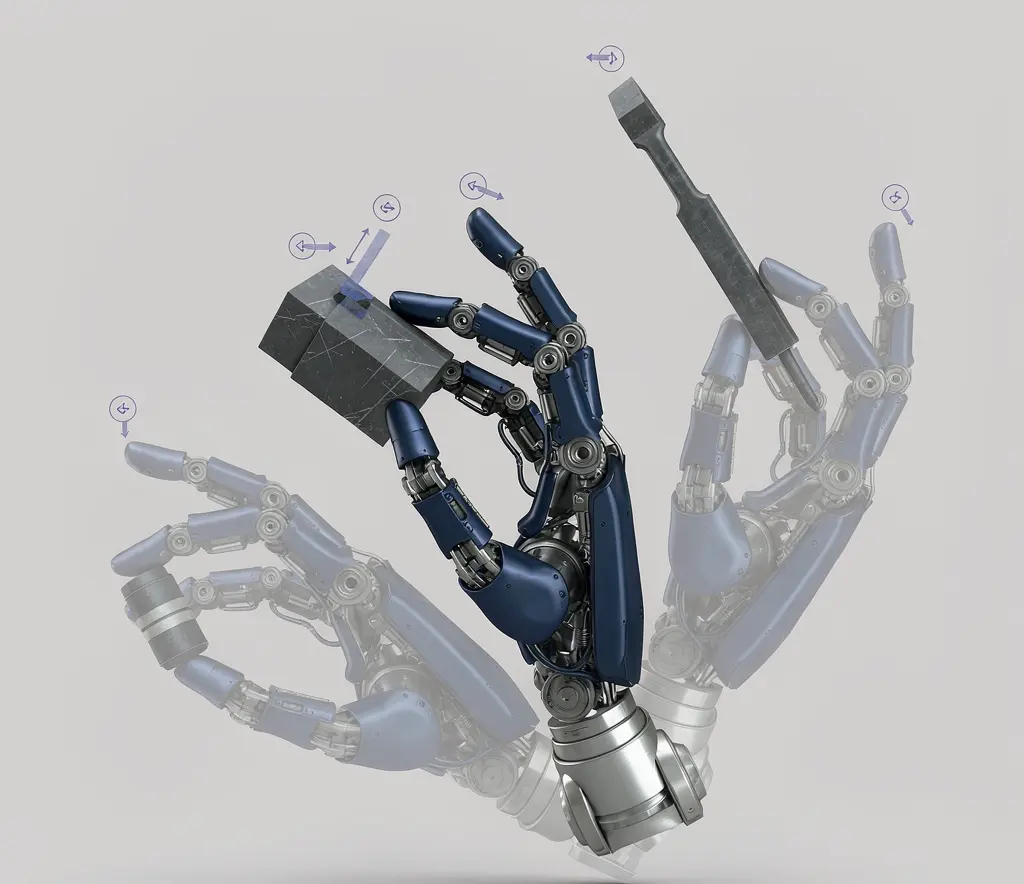
Humanoid Robot Hand Dexterity Verification: Grasp Set, Tool Use, Force Control, and Recovery
Oct 08, 2026

Industrial Exoskeleton Fit and Sizing: Anthropometry, Adjustment Time, PPE, and Shared-Device Programs
Oct 08, 2026

Robot Duty Cycle and Thermal Limits: Why Rated Payload and Speed Do Not Guarantee Continuous Operation
Oct 08, 2026
The most common mistake in AMR controller selection is making decisions based on chip computing power. Engineering teams that have built AMR platforms report: many engineers only look at chip specs, blindly pursuing high-performance chips while ignoring scenario fit. The biggest misconception is looking only at computing power, ignoring interface expansion.
Sufficient computing power but insufficient interfaces means you end up stacking adapter boards — leading to messy wiring, EMI issues, frequent disconnects, and positioning drift.
The controller is the AMR’s integration hub. It connects sensors (LiDAR, cameras, IMU, ultrasonics), actuators (motors, encoders), safety devices (safety lasers, e-stops), communication modules (Wi-Fi, 5G), and external interfaces (elevators, doors, WMS). The core selection question is not “how fast is the chip?” but “can it reliably connect all devices and process data in real time?”
Start from Sensors, Actuators, and Real-Time Buses
The correct selection order is to work backward from peripheral needs to interface requirements, then match computing power — not the other way around.
Step 1: List all devices that need to be connected
| Device category | Typical devices | Typical interface needs |
| Navigation sensors | 2D/3D LiDAR | Ethernet |
| Vision sensors | Depth cameras, industrial cameras | USB 3.0 / Ethernet / MIPI |
| Inertial sensors | IMU | SPI / I2C / UART |
| Auxiliary sensors | Ultrasonics, anti-drop | GPIO / ADC |
| Actuators | Motor drivers | CAN / RS485 / EtherCAT |
| Encoders | Wheel encoders | Quadrature / SPI |
| Safety devices | Safety LiDAR, e-stop | Safety relay / safety I/O |
| Communication | Wi-Fi, 5G modules | USB / Ethernet / UART |
| External interfaces | Elevators, doors, WMS | Ethernet / RS485 / Dry contact |
Step 2: Count interface quantities and types — not “does it have this interface?” but “are there enough for all devices?”
The core pain point from frontline engineers: computing power is sufficient but interface count is not. For example, a high-performance chip with only 2 USB ports and 1 Ethernet port, but your system needs 3 cameras + 2 LiDARs + 1 Wi-Fi module — not enough ports means adding USB hubs and network switches, increasing wiring complexity, EMI, and failure points.
CAN, RS485, Ethernet, USB, and Camera Interfaces
Different interface types play different roles in AMRs. Selection requires understanding their characteristics and limitations:
CAN bus: An example interface for industrial real-time communication, used for motor drivers, encoders, and other devices. Advantages: strong interference resistance, predictable real-time performance, multi-device bus sharing. Limitation: limited bandwidth — not suitable for high-bandwidth sensor data. Confirm device and protocol requirements with the supplier — other fieldbus or safety communication protocols may also be appropriate depending on the architecture.
RS485: Differential serial communication, relatively strong interference resistance, commonly used for drivers and simple sensors. Bandwidth lower than CAN FD, but simple wiring and low cost.
Ethernet: High-bandwidth communication, used for LiDAR, cameras, Wi-Fi modules, and upper-level system communication. Advantages: high bandwidth, versatility. Limitation: real-time performance not as good as CAN (unless using TSN Ethernet), switch chips add complexity.
USB: High-bandwidth general-purpose interface, commonly used for cameras and communication modules. Limitations: short connection distance in industrial environments, mechanical connection reliability lower than industrial connectors, hub cascading adds latency.
MIPI CSI: Embedded camera interface, high bandwidth, low latency, but only for onboard cameras, not for externally mounted industrial cameras.
Count how many of each interface type your system needs, leaving expansion margin for future sensor, safety, or communication additions. If interfaces are insufficient and adapter boards/hubs are needed, assess the impact on wiring, EMC, and reliability.
Isolation, EMC, and Industrial Reliability
A controller that works in the lab may frequently disconnect in the field. The difference is often not in computing power but in industrial reliability design.
Electrical isolation: In industrial environments, motor drivers, inverters, and grid interference can propagate through the bus to the controller. CAN/RS485 interfaces without electrical isolation may experience communication interruptions, data errors, or even chip damage in high-interference environments.
EMC design: Electromagnetic compatibility affects not only the controller itself but also sensor data quality. Frontline engineers report “messy wiring, EMI, frequent disconnects, positioning drift” — these problems are often not chip issues but EMC problems introduced by interface expansion methods (adapter boards, flying wires, hub cascading).
Industrial connectors: Pin headers used in labs may loosen in vibration environments. Industrial applications need locking connectors or at least latched connectors.
Thermal management: High-performance chips generate heat under load. In a sealed or semi-sealed AMR chassis, insufficient thermal design leads to chip throttling, system instability, or overheating protection. Confirm the thermal solution (passive or active) matches the controller’s power dissipation.
Environmental adaptability: Temperature range (commercial vs. industrial grade), humidity, vibration, and shock ratings — these do not show up in the lab but become stability bottlenecks in the field.
Onboard vs. External Interfaces and Safety-Rated Connections
Controller interfaces fall into different categories that require different design considerations:
| Interface category | Onboard (controller PCB) | External (chassis-mounted) | Safety-rated |
| Motor/encoder | CAN/EtherCAT on board | Terminal blocks or connectors | — |
| Navigation sensors | Ethernet ports | Industrial connectors | — |
| Safety LiDAR | Ethernet or dedicated safety bus | Safety-rated connector | Must use safety-rated interface per sensor requirement |
| E-stop | — | Safety relay chain | Hardwired safety circuit, not software-dependent |
| Communication | USB/Ethernet on board | Antenna connectors | — |
| External equipment (elevators, doors) | RS485/dry contact | Terminal blocks | Elevator/door safety interlocks may require safety-rated interface |
Safety-rated interfaces (e-stops, safety LiDAR, safety interlocks) must use a validated safety architecture/protocol/interface — do not infer safety from connector type or assume a shared physical medium cannot support safety. Confirm with the supplier which interfaces are safety-rated, which safety protocol or architecture is used, and how the safety function is validated. This affects how you wire the safety circuit and whether the safety function can be bypassed by a communication failure.
Computing Power Needs for Mapping, Perception, and Local Planning
While interfaces matter more than computing power, computing power still needs to match the application scenario. The key is understanding how different navigation methods demand different levels of computing power:
| Navigation method | Computing demand | Typical chip level | Key bottleneck |
| Magnetic strip / QR code navigation | Low | Entry-level | Interface count, not computing |
| 2D LiDAR SLAM | Medium | Mid-range | LiDAR data processing + path planning |
| Vision + LiDAR fusion SLAM | High | High-end | Multi-sensor fusion + vision processing |
| Fleet dispatching (multi-robot coordination) | External/edge/server | Not onboard controller | Real-time multi-robot path planning + communication |
More computing power is not always better. An AGV doing only QR code navigation with a high-end chip wastes cost and adds thermal burden. An AMR doing vision-LiDAR fusion SLAM with an entry-level chip will have processing latency and navigation stuttering.
Simple QR code/magnetic strip navigation needs only entry-level chips; vision-LiDAR fusion SLAM needs higher computing power. But even with a high-power chip, if interfaces are insufficient and EMC design is inadequate, the system will still have problems.
Note: fleet dispatching and multi-robot coordination typically belong to an external/edge/server architecture, not the onboard vehicle controller. The onboard controller handles local perception and local planning — confirm with the supplier which computing functions are onboard and which are external.
Expansion Margin and Connector Strategy
Controller selection is not just about meeting current needs — future expansion must be considered.
Expansion need sources:
- Adding sensors (upgrading from 2D LiDAR to 3D LiDAR + vision fusion)
- Adding safety devices (upgrading from auxiliary sensing to safety-certified sensors)
- Adding external interfaces (expanding from single-floor to multi-floor elevator integration)
- Adding communication modules (upgrading from Wi-Fi to 5G)
- Software upgrades needing more computing (from simple path planning to reinforcement learning navigation)
Connector strategy:
- When onboard interfaces are insufficient, expansion options include: adapter boards (add ports but increase wiring and EMC risk), expansion boards (add I/O via industrial bus, more reliable but higher cost), external hubs (USB hub/network switch, simple but lowest reliability)
The lesson from frontline engineers: expansion should not be done by post-hoc stacking but by reserving interface margin during selection.
Why Adapter Boards and External Hubs Introduce Failure Points
Adapter boards and hubs are not “harmless expansion” — every intermediate link introduces new failure potential:
| Expansion method | Risk introduced | Failure symptom |
| USB hub | Bandwidth sharing, latency increase, power shortage | Camera disconnect, frame rate drop |
| Network switch chip | Configuration complexity, EMC sensitivity | Communication interruption, latency spikes |
| Adapter board | More wiring, more contact points, worse EMC | Intermittent communication faults, positioning drift |
| Flying wires / DuPont connectors | Vibration loosening, poor contact | Random faults, hard to reproduce |
| CAN/RS485 splitting | Bus load increase, termination resistor mismatch | Communication errors, bus lockup |
If the controller needs a large number of adapter boards and hubs at selection stage to meet interface requirements, the controller’s interface configuration does not match your application. The right approach is to choose a controller whose interface configuration is closer to your needs, not to force-fit with expansion methods.
OEM Project Controller Requirements Matrix
| Interface category | Specific device | Quantity | Interface type | Bandwidth/speed need | Real-time requirement | Safety-rated? | Expansion margin |
| Navigation sensors | |||||||
| 2D LiDAR | ___ | Ethernet | ___ Mbps | Medium | No | +1 | |
| 3D LiDAR | ___ | Ethernet | ___ Mbps | Medium | No | +1 | |
| Depth camera | ___ | USB 3.0/Eth | ___ Mbps | Low | No | +1 | |
| Inertial and auxiliary | |||||||
| IMU | ___ | SPI/I2C | ___ | High | No | — | |
| Ultrasonics | ___ | GPIO/ADC | — | Low | No | +2 | |
| Drive and encoders | |||||||
| Motor driver | ___ | CAN/RS485 | ___ | High | No | — | |
| Wheel encoder | ___ | Quadrature/SPI | ___ | High | No | — | |
| Safety devices | |||||||
| Safety LiDAR | ___ | Ethernet/safety I/O | ___ Mbps | High | Yes | — | |
| E-stop | ___ | Safety relay | — | Highest | Yes | — | |
| Communication | |||||||
| Wi-Fi module | ___ | USB/Eth | ___ Mbps | Low | No | — | |
| 5G module | ___ | USB/Eth | ___ Mbps | Low | No | — | |
| External interfaces | |||||||
| Elevator/door | ___ | RS485/dry contact | — | Medium | Depends | +1 | |
| WMS/MES | ___ | Ethernet | ___ Mbps | Low | No | — | |
| Computing needs | |||||||
| Navigation algorithm | ___ | — | ___ TOPS | — | — | Reserve margin | |
| Perception processing | ___ | — | ___ TOPS | — | — | Reserve margin | |
| Path planning | ___ | — | ___ | — | — | Reserve margin | |
| Industrial reliability | |||||||
| Operating temperature | °C to °C | ||||||
| Electrical isolation needs | ☐ CAN ☐ RS485 ☐ Other | ||||||
| Vibration/shock rating | ___ | ||||||
| Thermal solution | ☐ Passive ☐ Active fan | ||||||
| Connector type | ☐ Industrial locking ☐ Standard |
Need to Review AMR Controller I/O?
A controller should match the sensors, drives, safety architecture, and expansion plan—not just a compute benchmark. We can help review the interface allocation before hardware is locked.
Please share, if available: sensor and actuator list, required CAN or serial buses, Ethernet and USB count, safety interfaces, Wi-Fi or 5G modules, WMS/MES connection, and future expansion plan.
Send I/O RequirementsController Specification Inputs
- Work backward from peripheral needs to interface requirements — list all sensors, actuators, safety devices, and communication modules first, then count interfaces.
- Interface count matters more than chip computing power — insufficient interfaces means stacking adapter boards, introducing EMC issues and failure points.
- Reserve expansion margin — future sensor, safety, or communication additions should not require a controller swap.
- Industrial reliability design is not optional — electrical isolation, EMC design, thermal management, and connector type directly determine field stability.
- Match computing power to navigation method — QR code navigation does not need a high-end chip; vision fusion SLAM and fleet dispatching need more.
- Assess the hidden costs of adapter boards/hubs — every intermediate link is a potential failure point. Do not select a controller whose interface configuration does not match.
- Ask the supplier for an interface allocation diagram and EMC test data — not just the chip spec sheet.
Share on Social:


Contact Us
In This Article
Reusable Pallets for Autonomous Handling: Repair, Replace, or Standardize the Carrier Fleet?
Oct 10, 2026
Humanoid Robot Hand Dexterity Verification: Grasp Set, Tool Use, Force Control, and Recovery
Oct 08, 2026
Industrial Exoskeleton Fit and Sizing: Anthropometry, Adjustment Time, PPE, and Shared-Device Programs
Oct 08, 2026
Robot Duty Cycle and Thermal Limits: Why Rated Payload and Speed Do Not Guarantee Continuous Operation
Oct 08, 2026