

 Contact Us

 Home /
 Robot Design Review Gates: What Buyers Should Freeze at PDR, CDR, and Before Build
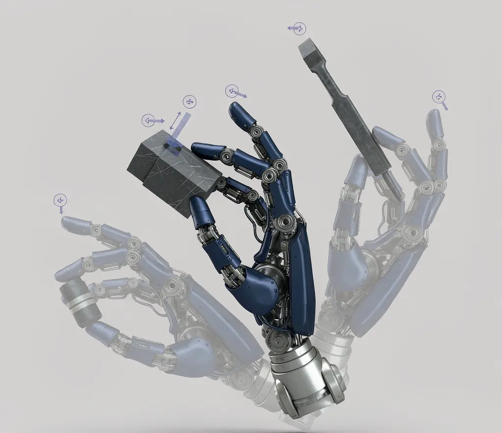
Humanoid Robot Hand Dexterity Verification: Grasp Set, Tool Use, Force Control, and Recovery
Oct 08, 2026

Industrial Exoskeleton Fit and Sizing: Anthropometry, Adjustment Time, PPE, and Shared-Device Programs
Oct 08, 2026

Robot Duty Cycle and Thermal Limits: Why Rated Payload and Speed Do Not Guarantee Continuous Operation
Oct 08, 2026

Robot IP Ratings Explained: What IP54, IP65, and IP67 Do — and Do Not — Prove
Oct 08, 2026
A robot automation project reaches a point where the concept must become hardware. That transition is where design review gates come in. A design review is not a single approval meeting where everything is checked at once. Mechanical layout, software architecture, safety design, and interface definitions mature at different rates. Freezing all of them at the same time either delays the project unnecessarily or, more dangerously, freezes immature designs that are not ready for manufacturing. This article explains how to structure design review gates so that each discipline is frozen only when its evidence is ready, and how buyers can participate in those gates without turning them into rubber-stamp sessions.
Why One Design Approval Meeting Is Not Enough
In practice, robot cell design involves multiple disciplines that do not mature simultaneously. The mechanical layout may be stable early, because it depends on the robot model, floor space, and part presentation, which are usually defined before the project starts. The safety design may take longer, because it depends on risk assessment results that require knowing the full motion envelope and interaction scenarios. Software and control architecture may continue to evolve as interface specifications are finalized with IT, MES, or WMS teams. EOAT design depends on part characteristics that may not be fully defined until sample parts are available.
If all these disciplines are approved in a single meeting, one of two things happens. Either the meeting approves everything, including items that are not ready, and unresolved issues are carried into manufacturing. Or the meeting identifies problems but has no mechanism to gate specific disciplines, so the entire project waits while one issue is resolved. Structured review gates solve this by defining what must be ready before each gate and allowing disciplines to mature independently within a controlled framework.
PDR and CDR as Adaptable Review Gates
Two review gates are commonly used in engineering projects: the Preliminary Design Review (PDR) and the Critical Design Review (CDR). These terms originate in systems engineering practice. NASA's NPR 7123.1D (the current version, which supersedes NPR 7123.1C) defines life-cycle phases and technical reviews in Chapter 5. Phase B corresponds to preliminary design, and Phase C corresponds to final design and fabrication. Key Decision Points (KDPs) separate the phases. ISO/IEC/IEEE 15288:2023, the international standard for system lifecycle processes, defines design review, verification, and validation as lifecycle activities without prescribing a specific lifecycle model or review cadence.
These are systems engineering references, not commercial robot project regulations. A robot buyer does not need to adopt NASA's full life-cycle framework. What is useful is the principle: define what evidence must be assembled before design proceeds from concept to detailed design (PDR), and from detailed design to manufacturing (CDR), and use those evidence packages as decision gates.
PDR: architecture and feasibility maturity
The PDR evaluates whether the proposed architecture is feasible and the major design choices are sound. At PDR, the following should be assessed:
- Process flow and cycle time concept: Does the proposed sequence of operations achieve the required throughput? Is the cycle time estimate based on representative motion or on optimistic assumptions?
- Robot model and configuration: Is the selected robot rated for the payload, reach, and precision required? Is the mounting orientation (floor, wall, ceiling, inverted) confirmed?
- Major interfaces: Are the interface definitions for power, air, network, and data sufficiently detailed to proceed with detailed design? Are the interface owners identified?
- EOAT concept: Is the end-of-arm tooling approach defined? Is the gripper or tool type selected, even if specific dimensions are not finalized?
- Safety concept: Has the initial risk assessment been performed? Are the safety functions identified (e.g., area scanners, light curtains, safety-rated stops)?
- Verification strategy: Is there a plan for how requirements will be verified at FAT and SAT?
- Risk register: Are the top technical risks identified, with mitigation plans?
The PDR does not require final drawings or finalized BOMs. It requires enough definition to confirm that the approach is viable and that the major unknowns have been identified.
CDR: build and integration readiness
The CDR evaluates whether the design is mature enough to proceed to manufacturing and integration. At CDR, the following should be reviewed:
- Final BOM and drawings: Are the mechanical drawings released for fabrication? Is the BOM complete, including all purchased components, fasteners, and consumables?
- Software and interface versions: Are the control software version, PLC program version, and interface specifications (ICDs) frozen? Are any software items still marked as “to be developed”?
- Safety design: Is the safety circuit finalized, including all safety-rated components, their performance level or safety integrity level, and the safety function architecture?
- Test plan: Is the FAT test plan written, with test procedures, pass/fail criteria, and required test parts? Is the SAT plan outlined?
- Open items list: Are all open items from PDR resolved or have documented closure plans?
- Anomaly and deviation log: Are any known deviations from the original requirements documented, with buyer acknowledgment?
The CDR is the last point where design changes are inexpensive. After CDR, changes require rework of fabricated parts, reprogramming, or reordering of components. The gate exists to ensure that the design is genuinely ready, not that the schedule demands it.
What Must Be Frozen—and What Can Remain Site-Specific
Not everything needs to be frozen at CDR. The principle is to freeze what is needed to manufacture and build, while leaving site-specific parameters as controlled variables. Items that should be frozen include:
- Robot model, configuration, and mounting orientation
- EOAT design (gripper or tool drawings)
- Mechanical interface dimensions (base plate, tool changer mounting)
- Control architecture and communication protocol versions
- Safety function design and component selection
- BOM for all fabricated and purchased items
Items that can remain as controlled parameters, to be finalized during installation or commissioning, include:
- Site-specific IP addresses and network configuration
- Floor coordinate mapping for AMRs
- Robot program parameters that depend on actual part variants (e.g., torque thresholds, force limits)
- Calibration values that can only be determined on-site
The distinction is that frozen items are part of the build baseline. Changing them after CDR requires a formal change order. Site-specific parameters are expected to be defined during commissioning and do not require a change order, but they should be documented in the commissioning records.
Entrance Package for Each Review
A design review is only as good as the material available before the meeting. The entrance package should be delivered to reviewers at least several days before the review date. For PDR, the package includes:
- Requirements baseline (current version of the URS or requirements list)
- System architecture diagram
- Preliminary layout drawing
- Interface register (list of all interfaces, their types, and owners)
- Robot model selection rationale
- Risk register
- Verification strategy outline
- Action items from any prior reviews
The robot project statement of work establishes deliverables and responsibilities that feed into the design-review package.
For CDR, the entrance package expands to include:
- Final layout drawing
- Released mechanical drawings for fabrication
- Complete BOM
- Interface control documents (ICDs) with version numbers
- Software architecture and version plan
- Safety design documentation (risk assessment, safety function specification)
- FAT test plan with procedures and pass/fail criteria
- Updated risk register
- Open items list with closure status
- Deviation log (if any requirements have been accepted as deviations)
Go, Conditional Go, and Hold Criteria
A design review results in one of three outcomes:
- Go: The design is approved to proceed to the next phase. All entrance package items are complete, and no blocking issues remain.
- Conditional Go: The design is approved to proceed, but specific conditions must be met within a defined timeframe. Each condition has a named owner, a due date, and a description of what must be delivered. The conditions are tracked as action items and reviewed before the next gate.
- Hold: The design is not approved to proceed. One or more blocking issues must be resolved before the review is reconvened. A hold should be used when proceeding would commit resources to a design that may need to change fundamentally.
The key discipline is that a Conditional Go is not a Go with informal promises. Each condition is documented with an owner, a due date, and a clear definition of what evidence will close the condition. If the condition is not closed by the due date, the project team must decide whether to extend the deadline (with a documented reason) or revert to a Hold.
Blocking vs non-blocking open items
Not every open item blocks progress. A blocking item is one where proceeding to the next phase would commit resources to a design that may need to change if the item is resolved unfavorably. For example, if the robot's payload capacity is uncertain because the EOAT weight is not finalized, proceeding to fabricate the mounting plate is risky. The EOAT weight must be confirmed before the plate is built.
A non-blocking item is one where the design can proceed with a documented assumption that can be verified or adjusted later. For example, if the exact network IP scheme is not yet defined, the robot can be built and tested with a temporary IP, and the final IP can be configured during commissioning. The assumption is documented, and the verification is assigned to the commissioning phase.
The distinction requires engineering judgment. The review board should explicitly classify each open item as blocking or non-blocking, rather than leaving the classification implicit.
Handling Design Assumptions and Open Actions
Design assumptions are inevitable. The robot model is selected based on a payload estimate. The cycle time is projected based on a motion path that has not been physically tested. The safety zone is sized based on a robot speed that may change during commissioning. These assumptions are not problems in themselves. The problem arises when assumptions become treated as facts without being verified.
The RTM and the risk register work together to manage assumptions. Each assumption is recorded as an open item with a verification plan. If the assumption is that the EOAT will weigh 3 kg, the verification is to weigh the completed EOAT. If the assumption is that the cycle time will be 15 seconds, the verification is to measure the cycle time during FAT with representative parts and motion. The assumption remains open until the verification is executed and the result confirms or corrects it.
Third-party dependencies are a special case. If the project depends on a network configuration from the buyer's IT department, or on a part specification from the buyer's product engineering team, the dependency is recorded with an owner and a due date. If the third party does not deliver on time, the project team must decide whether to proceed with an assumption or hold.
A robot project risk register can track the uncertainty behind unresolved design assumptions without replacing the gate decision.
What the Buyer Should Request in a Design Review Pack
A buyer who is not the design authority still has a critical role at design reviews. The buyer's interest is in confirming that the design will meet the requirements that were agreed in the RFP and URS. To do this effectively, the buyer should request the following in the design review pack:
- Requirement baseline: The current version of the requirements list, with any changes since the RFP highlighted and explained
- System diagram: A block diagram showing all major components and their connections
- Layout drawing: The cell or station layout, showing robot position, part presentation, operator access, and safety zones
- ICD (Interface Control Document): The document defining all interfaces between the robot system and external systems (PLC, WMS, MES, IT network)
- BOM: The bill of materials, at least at the assembly level for PDR and at the component level for CDR
- Software revision plan: The planned software versions for robot controller, PLC, and any application software
- Safety concept: The risk assessment and safety function design
- Test strategy: The plan for FAT and SAT, including what will be tested, how, and with what pass/fail criteria
- Action closure list: All open items from prior reviews, with current status and closure plans
An approved robot interface control document provides a controlled reference for the integration boundaries examined at CDR.
Design Freeze Failure Patterns
The following scenarios are illustrative of how design freezes can fail. They are not drawn from any specific project but represent patterns that occur in practice.
In one pattern, a robot cell is approved at CDR with the API interface marked as “to be confirmed.” The integrator proceeds to build the cell. When the buyer's IT team eventually provides the API specification, it requires a different communication protocol than the one the cell was built for. The cell must be reworked, and the schedule slips by weeks. The root cause is that an interface that should have been a blocking item was treated as a non-blocking assumption.
In another pattern, a robot is selected based on a payload estimate that includes the EOAT. At CDR, the EOAT design is still preliminary, and the weight estimate is 2.5 kg. After CDR, the EOAT is finalized at 3.8 kg due to additional sensors and a heavier gripper. The robot's rated payload is exceeded, and a larger robot model is required. The mounting plate, already fabricated, does not fit the new robot. The root cause is that the EOAT weight was an assumption that was not verified before the mounting plate was committed to fabrication.
In a third pattern, a fixture design is approved at CDR based on drawings that show the part in its nominal position. When the fixture is built and tested with actual parts, the parts vary more than expected from the nominal. The fixture cannot hold the parts reliably, and the robot cannot achieve the required positioning accuracy. The root cause is that the fixture design was frozen without testing with representative parts that included the full tolerance range.
These patterns share a common thread: a design element was frozen before the evidence needed to confirm it was ready. The design review gate exists to prevent this, but only if the gate is enforced with real criteria and not bypassed by schedule pressure.
Once the design baseline is approved, changes that alter the agreed scope may require robot project change orders.
Preparing a robot cell for PDR or CDR? Share the planned robot configuration, connected PLC or WMS/MES systems, interface list and open integration questions. AIsirRobot can help organize the interface information and responsibility gaps for manufacturer and integrator follow-up; it does not approve detailed designs or carry out commissioning.
Share on Social:


Contact Us
In This Article
Humanoid Robot Hand Dexterity Verification: Grasp Set, Tool Use, Force Control, and Recovery
Oct 08, 2026
Industrial Exoskeleton Fit and Sizing: Anthropometry, Adjustment Time, PPE, and Shared-Device Programs
Oct 08, 2026
Robot Duty Cycle and Thermal Limits: Why Rated Payload and Speed Do Not Guarantee Continuous Operation
Oct 08, 2026
Robot IP Ratings Explained: What IP54, IP65, and IP67 Do — and Do Not — Prove
Oct 08, 2026