Contact Us



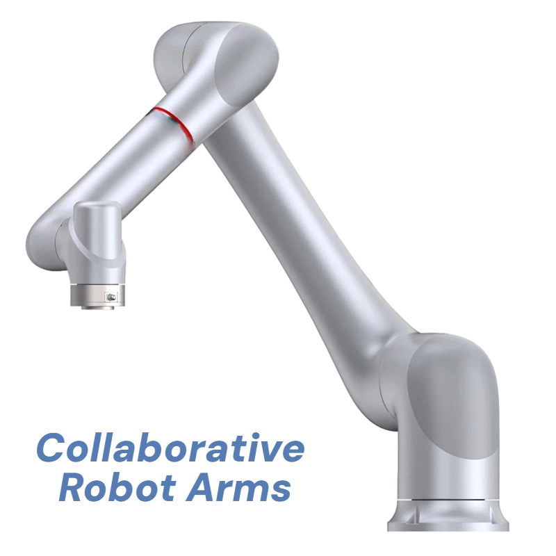
Collaborative Robot Arms
AIsirRobot selects and integrates collaborative robot arm systems for machine tending, assembly, packaging, inspection, welding, and other repeatable production tasks. We combine the selected platform with application-specific EOAT, vision, controls, and safeguarding, then validate reach, cycle time, interfaces, and acceptance criteria for your production line. Two 6-axis cobot platforms are available: a 5 kg payload model for light, precise operations and a 12 kg payload model with 1434 mm reach for broader workspaces. Each platform can be configured into a complete application through EOAT, vision, safety controls, and line interface integration.



Product Overview
Collaborative robot arms fit a specific range of applications. Use this checklist before committing to a cobot-based solution.
A cobot may be a good fit when:
- The task is repetitive and involves moderate payload (within the robot’s rated capacity including EOAT and workpiece)
- The process benefits from force control, compliant motion, or hand-guided teaching
- The production line requires frequent changeovers or low-volume, high-mix handling
- The workspace cannot accommodate full industrial robot guarding
- Operators and robots share the same workspace for part of the cycle
A cobot may not be the right choice when:
- The application requires very short cycle times beyond cobot speed limits
- Payload or inertia exceeds the cobot’s rated capacity after adding EOAT, workpiece, and tooling
- The process involves sharp tools, high temperatures, or high-speed material ejection
- The task requires large workspace coverage that exceeds the cobot’s reach envelope
- The application needs continuous high-speed operation better suited to traditional industrial robots
In borderline cases, the decision depends on the application risk assessment, cycle time targets, and workspace constraints. A feasibility review helps clarify whether a cobot or an industrial robot is the better platform.
 Photo
Photo
Platform Selection: 5 kg vs. 12 kg
| Decision Field | AIsirRobot 5 kg Cobot | AIsirRobot CR12-12/1.4C |
| Payload | 5 kg | 12 kg |
| Working Radius | 919 mm | 1434 mm |
| IP Rating | IP54 | IP67 |
| Repeatability | ±0.03 mm | ±0.03 mm |
| Mounting | Any orientation | Any orientation |
| Typical Applications | Benchtop assembly, lab automation, small-part handling, inspection | Machine tending, packaging, palletizing, welding, surface finishing |
| Environment Fit | Standard indoor industrial | Dust, coolant, or liquid splash exposure |
Applications
✅ Machine Tending
Task: Loading and unloading CNC machines, lathes, and presses. The robot handles workpiece placement, chuck or clamp interaction, door operation, cycle start signals, and part removal.
Integration items: Machine door dimensions, chuck access, gripper clearance, I/O handshake, fault recovery logic.
Key inputs: Workpiece geometry and weight, target cycle time, machine interface type, part presentation method.
Validation: Reach into the machine work area, grip reliability, cycle time, and fault recovery are tested during simulation and FAT.
✅ Assembly and Fastening
Task: Screwdriving, press-fit, snap-fit, and component insertion. The built-in force control supports compliant assembly where position-only robots may damage parts.
Integration items: Gripper or screwdriver weight, part center of gravity, feed mechanism, insertion force profile.
Key inputs: Part dimensions, required insertion force, feed rate, tolerance spec.
Validation: Insertion force consistency, cycle time, and defect rate are confirmed during application testing.
✅ Packaging and Pick-and-Place
Task: Case packing, palletizing, and sorting. The CR12-12/1.4C’s 12 kg payload and 1434 mm reach suit larger workpieces and pallet patterns.
Integration items: Pallet pattern, conveyor timing, grip and release sequence, reach envelope.
Key inputs: Workpiece weight and dimensions, pallet dimensions, conveyor speed, layers per pallet.
Validation: Cycle time, pattern completeness, and conveyor synchronization are verified during FAT.
✅ Surface Finishing
Task: Sanding, polishing, deburring, and dispensing. The adjustable stiffness range and 0.5 N force precision are designed to support consistent contact force across contoured surfaces in suitable applications.
Integration items: Tool weight, spindle type, contact force setting, media wear rate, path compensation.
Key inputs: Workpiece surface geometry, required surface finish, tool type, media specification.
Validation: Contact force consistency, surface finish quality, and tool wear behavior are assessed during process testing.
✅ Inspection and Testing
Task: Vision-guided dimensional inspection, presence verification, and functional testing.
Integration items: Camera type and mounting (on-arm or fixed), lighting, part presentation, tolerance requirements.
Key inputs: Inspection features, tolerance spec, cycle time, part presentation method.
Validation: Measurement accuracy, false reject rate, and cycle time are confirmed during application testing.
✅ Welding
Task: Collaborative welding for small to medium batch sizes. The robot executes programmed weld paths while the operator manages fixture loading and part inspection.
Integration items: Welding power source interface, torch geometry, wire feed system, fume extraction, fixture design.
Key inputs: Material type and thickness, weld specifications, joint geometry, batch size.
Validation: Weld quality, path accuracy, safety validation (including arc flash, fume, and heat exposure), and power source communication are confirmed during FAT and SAT. Collaborative welding does not eliminate traditional welding hazards; appropriate safeguarding and ventilation are required.
Integration Considerations by Application
| Application | Key Integration Variables |
| Machine Tending | Door dimensions, chuck access, I/O handshake, fault recovery, cycle time |
| Assembly | Gripper weight, part center of gravity, insertion force, feed mechanism |
| Packaging | Pallet pattern, conveyor timing, grip sequence, reach envelope |
| Surface Finishing | Tool weight, spindle type, contact force, media wear, path compensation |
| Inspection | Camera type and mounting, lighting, part presentation, tolerance spec |
| Welding | Power source interface, torch geometry, wire feed, fume extraction, fixture |
Integrated System Scope
A cobot application is more than the robot arm. The complete system typically includes:
| Component | Role | Selection Basis |
| Robot platform | Motion, force sensing, safety functions | Payload, reach, IP, mounting, cycle time |
| End-of-arm tooling (EOAT) | Grips, positions, or processes workpiece | Workpiece weight, geometry, surface, force, cycle time |
| Vision system | Guides picking, inspects parts, verifies position | Part features, tolerance, lighting, camera mounting |
| Safety controls | Monitors human-robot interaction, enables collaborative modes | Risk assessment, workspace layout, applicable standards, operator access |
| PLC and line interfaces | Connects robot to machines, conveyors, factory systems | Protocol, I/O mapping, handshake logic, fault recovery |
| Fixtures and base | Positions workpieces, mounts robot | Workpiece geometry, tolerances, floor loading, vibration |
Each component is selected based on the application requirements and validated together during integration. Compatibility with existing machines, PLCs, or conveyors is confirmed through mechanical, signal, communication, and safety-interface review.
Technical Differentiators
The following platform capabilities are available on the selected models. Performance values are confirmed for the specific application, tool, and process conditions during integration.
✔️ Force-Torque Sensing and Collision Detection
Both platforms use force-torque sensor-based collision detection. Sensor information is monitored through dual-channel redundancy with an independently certified safety controller.
Brake-based position hold with dynamics feedforward compensation maintains position accuracy during power-on and power-off transitions.
What this means for your line: The safety functions are integrated into the platform rather than added externally. Your application risk assessment starts from a platform with built-in safety capabilities, not from a blank baseline.
✔️ Unified Force-Position Hybrid Control
A force-position hybrid control framework provides adjustable Cartesian stiffness across the full range (0–3000 N/m for the 5 kg model; 0–18000 N/m for the CR12-12/1.4C). Built-in joint torque sensing at every axis enables force control with 0.5 N / 0.1 Nm precision.
Integrated force-control process packages support fine polishing, precision assembly, and contact-sensitive operations without additional expansion modules.
What this means for your line: For contact tasks where position-only robots damage parts or require external compliance devices, the built-in force control can reduce the need for separate compliance hardware in suitable applications.
✔️ Motion Control
The control system uses trajectory optimization, dynamics-based path accuracy, and multi-axis coordination to maintain programmed paths under payload. A custom motor drive system supports payload motion capability.
What this means for your line: The robot is designed to maintain programmed paths under real loads rather than slowing down or deviating. Actual cycle time and path accuracy are confirmed during simulation and acceptance testing for the specific application.
✔️ Programming and Deployment
The platform supports 1 N drag-force teach-in for both point-to-point and continuous trajectory teaching. Flowchart-based graphical programming enables operator training without prior robotics experience. An offline programming software tool supports simulation across all models.
A controller-free design option is available for applications where reduced system footprint and flexible installation are priorities.
What this means for your line: For facilities that need to redeploy robots between stations or bring automation to space-constrained lines, the graphical programming and hand-guiding approach supports operator-led deployment. The controller-free option can reduce system footprint for suitable configurations.
✔️ Reliability
The platform undergoes design verification testing and factory acceptance testing before shipment. MTBF data is available from the platform manufacturer.
IP67 protection on the CR12-12/1.4C suits industrial environments with dust or liquid exposure. IP54 on the 5 kg model fits standard indoor industrial use. IP rating applicability to specific media (such as cutting fluids or coolants) is subject to media compatibility and installation review.
What this means for your line: The platform is engineered for industrial deployment. MTBF is a statistical reliability indicator, not a single-unit service life or maintenance interval. Actual uptime depends on the application, environment, maintenance schedule, and operating conditions.
Delivery Process
A typical cobot integration project follows these stages. Each stage produces defined deliverables that support project tracking and acceptance.
| Stage | Activities | Deliverables |
| 1. Requirement Review | Collect workpiece, cycle time, shift pattern, current process, quality requirements | URS or requirement confirmation form, preliminary risk and ROI assumptions |
| 2. Application Concept | Define candidate robot model, EOAT, vision, safety, and line interface options | Layout sketch, BOM scope, interface list, responsibility matrix |
| 3. Simulation and Validation | Verify reach, cycle time, collision, and path feasibility through simulation | Simulation assumptions, cycle time report, sample test plan |
| 4. Factory Acceptance Test (FAT) | Test the configured system at the build site against agreed criteria | Approved acceptance criteria, test records, issue closure log |
| 5. Site Acceptance Test (SAT) | On-site installation, commissioning, safety validation, and operator training | SAT records, safety validation documents, training sign-off |
| 6. Post-Installation Support | Documentation, spare parts guidance, remote or on-site support | Warranty terms, response channel, spare parts list, version/change records |
Indicative robot platform lead time: 35 days. Project lead time is confirmed after integration scope, component availability, validation requirements, and on-site work are defined.
Validation Evidence
Every cobot integration project is validated against agreed acceptance criteria before site acceptance. The validation process covers:
- Reach and workspace verification — Robot motion paths, singularities, and collision zones are checked in simulation and confirmed on the physical setup.
- Grip and tool performance — EOAT grip reliability, force profiles, and tool function are tested against the workpiece under production conditions.
- Cycle time measurement — Actual cycle time is measured using the proposed layout, motion path, peripheral equipment timing, and safety speed limits.
- Safety function validation — Safety functions (collision detection, emergency stop, protective stop) are tested per the application risk assessment and applicable standards.
Test records, acceptance documentation, and issue closure logs are archived per project and provided to the client. FAT and SAT protocols define the acceptance criteria, test methods, and sign-off responsibilities before the system is released for production.
Safety and Compliance
Collaborative Operation and Safeguarding
“Collaborative” describes the robot’s built-in safety functions and operating modes. It does not automatically mean any application can run without physical guarding.
Whether guarding, safety scanners, interlocks, or power-and-force-limiting modes are required is determined through an application-level risk assessment that considers:
- The robot and its operating speed
- End-of-arm tooling (weight, edges, pinch points)
- Workpiece (weight, shape, material, temperature)
- Contact forces and possible injury zones
- Workspace layout and operator access patterns
- Applicable regional regulations and industry standards
Depending on the task and risk assessment, the solution may use safety-rated monitored stop, hand guiding, speed and separation monitoring, power and force limiting, or conventional guarding and interlocks.
Standards and Certifications
The platforms are designed to comply with the following safety standards:
| Standard | Scope | Note |
| ISO 10218-1 | Safety requirements for industrial robot manufacturers | Applies to the robot platform |
| ISO 10218-2 | Safety requirements for robot applications and cells | Applies to the integrated workstation; closer to integrator responsibility |
| ISO/TS 15066 | Collaborative robot safety requirements and guidance | Technical Specification; provides guidance on collaborative operation |
| ISO 13849-1 | Functional safety of machine control systems | Performance Level and Category apply to safety-related control functions |
TÜV functional safety certifications have been obtained for the platform. Applicable safety documentation and certificates for the selected platform are provided for project review. Robot platform certifications cover the robot itself; the complete workstation, including tooling, fixtures, and safety devices, requires its own validation.
Standards compliance and certification applicability should be confirmed for the specific project location and industry requirements.
Frequently Asked Questions
Q1: Can these cobots be integrated with our existing machines or production line?
Integration with existing CNC machines, PLCs, conveyors, or other equipment requires a review of mechanical interfaces, I/O signals, communication protocols, safety circuits, cycle timing, workspace access, and fault recovery procedures. Compatibility is confirmed through interface and safety review, not assumed from the robot specification alone.
Q2: How do you select between the 5 kg and 12 kg models?
Effective payload must include the end-of-arm tooling, workpiece, cables, and connectors, with consideration for center of gravity, inertia, and mounting orientation. The 5 kg model suits benchtop assembly, lab automation, and light handling. The CR12-12/1.4C suits machine tending, packaging, and applications requiring longer reach (1434 mm) or IP67 protection. Final selection is based on the reviewed application requirements.
Q3: Does a collaborative robot always operate without guarding?
No. Whether physical guarding can be removed depends on the complete application risk assessment. Depending on the task, the solution may use safety-rated monitored stop, hand guiding, speed and separation monitoring, power and force limiting, or conventional guarding and interlocks.
Q4: What end-of-arm tooling can be integrated?
Grippers (pneumatic, electric, vacuum), welding torches, screwdrivers, sanding and polishing spindles, dispensing valves, and tool changers can be integrated. Tool selection is validated against workpiece weight, geometry, surface characteristics, required grip force, and cycle time.
Q5: How is cycle time confirmed?
Target cycle time is assessed using the proposed layout, motion path, peripheral equipment timing, safety speed limits, and equipment wait times, then confirmed during simulation and acceptance testing. Published robot axis speeds are maximum values; actual cycle time depends on the complete process.
Q6: What information do you need for a feasibility review?
Workpiece dimensions and weight, target cycle time, current process description, available workspace and layout, machine and equipment interfaces, environment conditions (temperature, dust, liquid), safety requirements, shift pattern, project location, and expected timeline.
Q7: How long does a cobot integration project take?
Indicative robot platform lead time is 35 days. Complete project lead time is confirmed after integration scope, component availability, validation requirements, and on-site work are defined. The feasibility review provides a project-specific timeline estimate.